
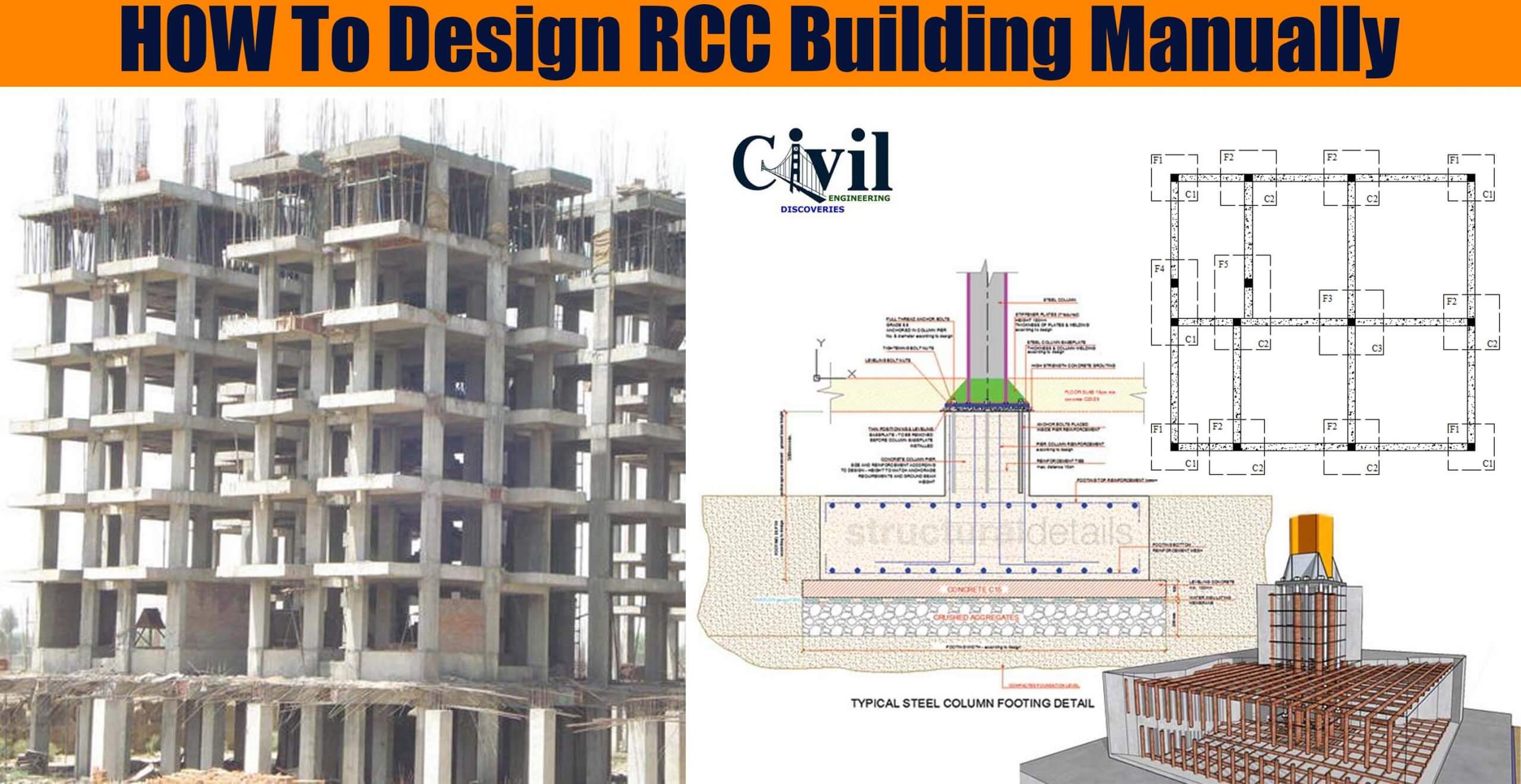
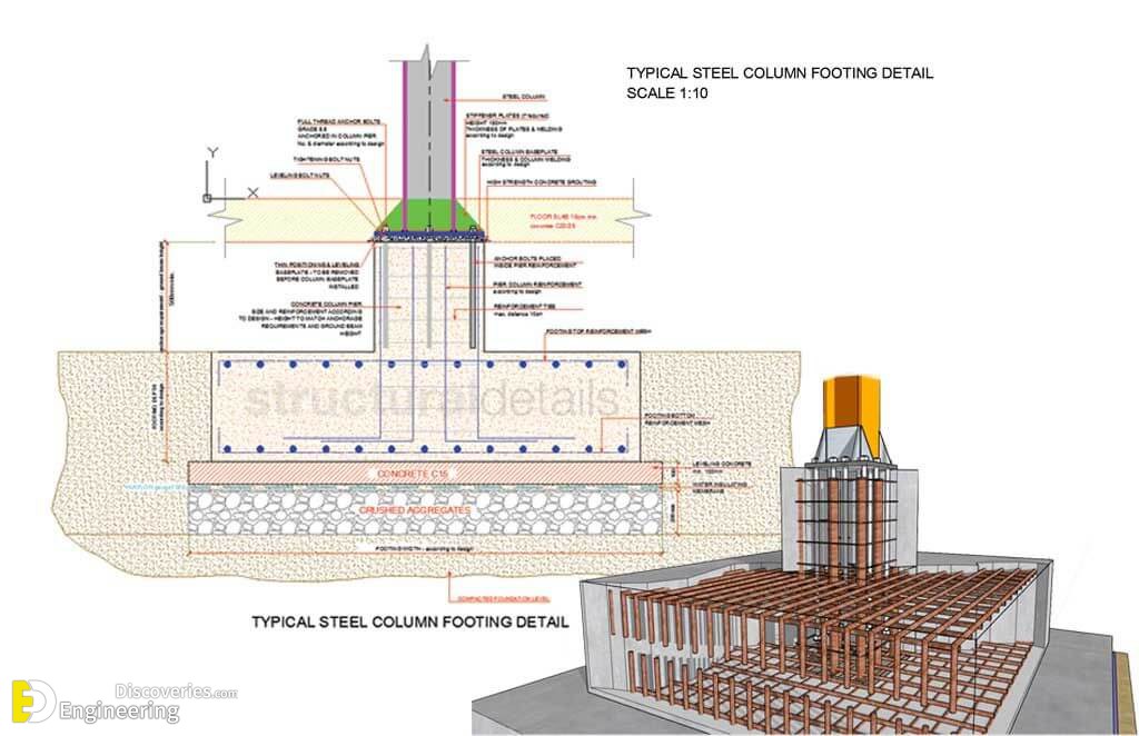
Let’s design for a typical plan of a 2BHK. And let’s only take dead and live loads. Add wind loads and seismic loads according to zone after practising with the dead and live load. The idea is simple – Slab rests on beams. Beams rest on columns and Columns rest on footings. So design slab first, then use the load from load to design beams. Beams will put the load on columns. And columns on footings.

Prerequisite:
Architectural plan
IS codes- 456, 875 (I and II)
Soil report
Scientific calculator
MS Excel- for faster calculations. Many design offices use the Excel template sheets. Don’t see them as designing software. They are just for faster calculations and minimize errors. Let’s start.
Architectural Plan
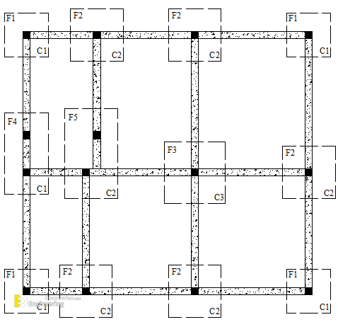
1- Mark columns.
2- Join columns to mark primary beams. There will be tertiary beams resting on primary beams.
3- Mark all beams. Number them.
4- Now mark slabs. Slabs with similar dimensions will be marked the same.
Slab load: For two-way slab load on the beam of length l = WL/3. Calculate slab load intensity for all 4 beams on which 2-way slab is resting. Units in KN/m (UDL). For one way slab WL/2 for the beams supporting the slab.
Self-weight Width of beam x Height of beam