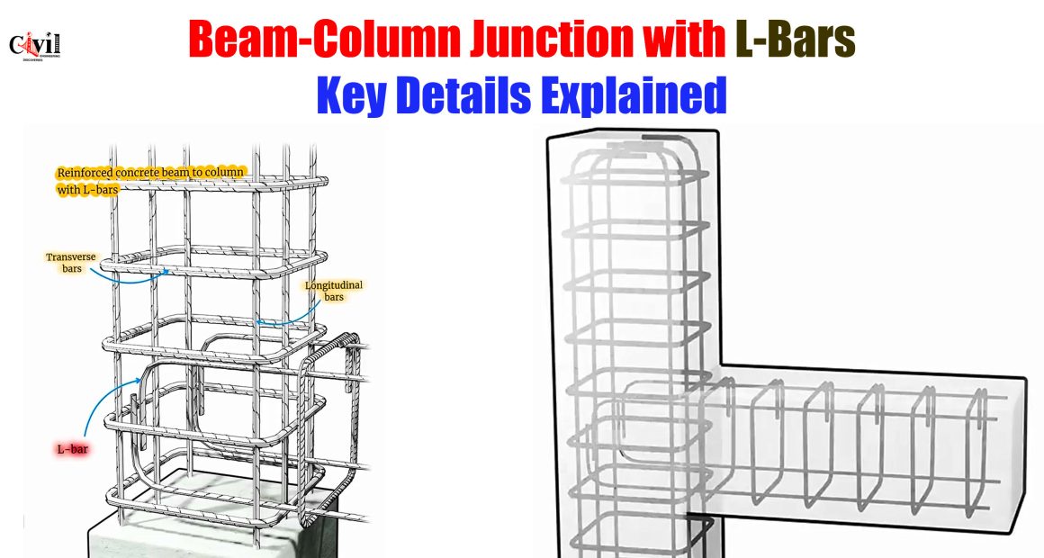
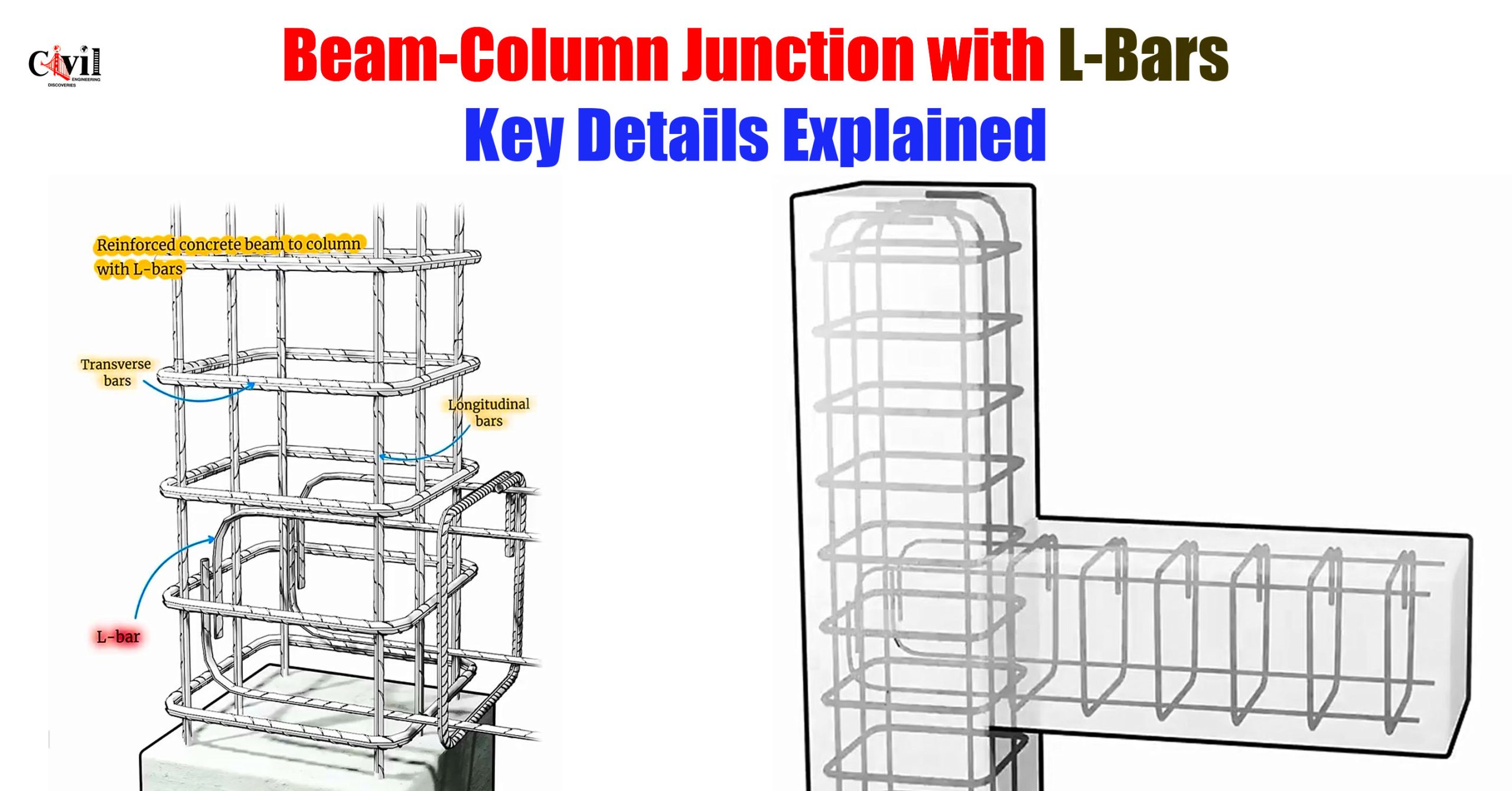
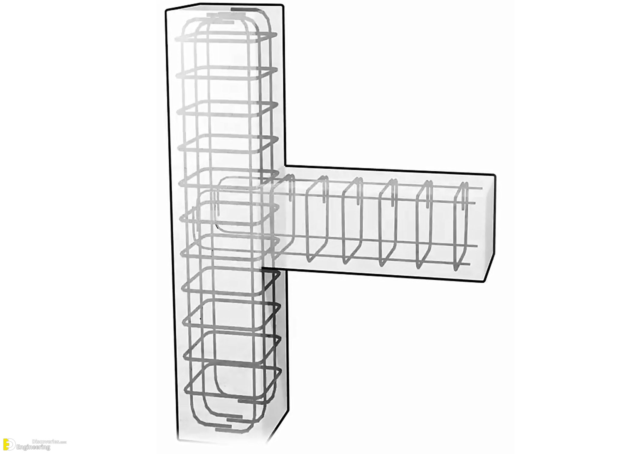
Beam-column junctions are among the most critical components in reinforced concrete structures. The strength, ductility, and integrity of a building often hinge on how these joints are designed and reinforced. One of the most effective techniques to enhance the performance of these junctions is the use of L-bars, which play a pivotal role in anchorage, load transfer, and seismic resistance. This article offers an in-depth look into the reinforcement detailing of beam-column junctions with a focus on L-bars, supported by a visually comprehensive image.
Understanding the Structural Importance of Beam-Column Junctions
Beam-column junctions are zones of high stress concentration. These are the points where vertical and horizontal structural elements intersect and interact under load. The way in which these forces transfer through the junction determines the safety of the entire structure. Poorly reinforced joints are prone to failure under lateral forces, especially during seismic events.
Anatomy of Reinforcement: Key Elements in the Junction
To fully comprehend the significance of L-bars, it’s essential to break down the various reinforcement components present in a typical beam-column joint:
1. Longitudinal Bars
These are the main reinforcement bars that run parallel to the column or beam length. They resist tensile and compressive forces, ensuring that the structural elements can handle vertical loads.
2. Transverse Bars
Also referred to as stirrups or ties, these bars encircle the longitudinal bars and are primarily responsible for shear resistance. They help confine the concrete and prevent buckling of longitudinal bars under axial load.
3. L-Bars
L-bars are critical for anchoring. These bars are bent at 90 degrees and extend into the joint, connecting beams to columns. Their role is to provide:
Proper anchorage
Efficient load transfer
Enhanced ductility
Improved seismic performance
Without L-bars, the development length of reinforcement may not be sufficient, especially at the joint, compromising the bond between steel and concrete.
The Role of L-Bars in Reinforced Concrete Beam-to-Column Connections
Enhanced Anchorage
One of the primary purposes of an L-bar is to anchor the beam reinforcement into the column. This anchorage is essential to ensure that the bar does not slip under load. The bent shape increases the bond strength and provides mechanical interlock with the concrete, enhancing overall connection rigidity.
Load Transfer Mechanism
At the junction, bending moments and shear forces are transferred from the beams to the columns. L-bars help in directing these forces smoothly, reducing the chances of stress concentration and potential cracking.
Seismic Resilience
In seismic zones, beam-column joints are subjected to reversal of forces and cyclic loading. L-bars contribute to energy dissipation by allowing slight ductile deformation, which is preferable over brittle failure. This ductility is crucial for the life-safety performance of structures.
Detailing Standards for L-Bar Placement and Spacing
Correct detailing of L-bars is paramount. Here are best practices based on IS 13920 (Ductile Detailing of RC Structures Subjected to Seismic Forces) and other international standards:
Minimum Embedment Length: L-bars must be embedded into the column to at least develop their full yield strength.
Proper Bend Radius: Sharp bends can cause stress concentration. A minimum bend diameter of 4-6 times the bar diameter is recommended.
Spacing: L-bars should be spaced closely enough to ensure uniform stress distribution, but not so close that they hinder concrete placement.
Cover Requirements: Adequate cover (typically 25-50 mm) must be provided to protect the bars from corrosion and fire.
Interpreting the Reinforcement Layout
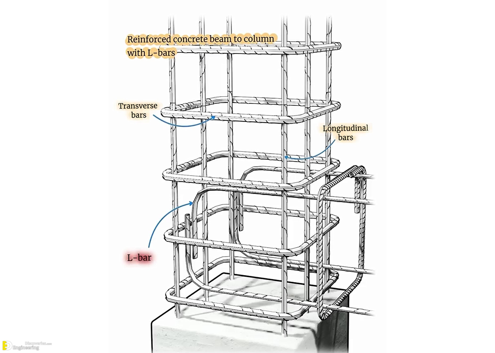
Reinforced concrete beam to column with L-bars: These L-shaped bars loop into the column core, effectively anchoring the horizontal beam bars into the vertical column structure.
Longitudinal bars: Vertical and horizontal bars provide primary reinforcement against bending and axial loads.
Transverse bars: These ties or stirrups wrap around the longitudinal bars and L-bars, confining the core concrete and enhancing shear resistance.
This image makes it abundantly clear how different reinforcement components work in synergy to deliver a structurally robust junction.
Practical Tips for On-Site Implementation
To ensure L-bars and beam-column reinforcement detailing meet design expectations, civil engineers and construction professionals should follow these on-site best practices:
Use bar bending schedules (BBS) for precise cutting and bending of L-bars.
Verify reinforcement alignment before concreting. Misaligned L-bars may reduce anchorage efficiency.
Use spacers and chairs to maintain correct cover and bar position during concrete pour.
Double-check bar overlaps and welding (if applicable), ensuring structural continuity.
Inspect bar cleanliness — remove rust, oil, or paint before installation to improve bond.
Advanced Design Considerations for Critical Structures
For high-rise buildings, bridges, or structures in seismic zones, further optimization of beam-column joints is essential:
Use of headed bars or mechanical anchorage systems in place of traditional L-bars for very congested joints.
Finite element modeling (FEM) to simulate stress flow and validate detailing design.
High-strength steel or corrosion-resistant bars (like epoxy-coated or stainless steel) for enhanced durability.
Hybrid reinforcement schemes using a combination of L-bars and straight bars with couplers.
Click Here To See Types Of Shear Reinforcement In Reinforced Concrete Slabs
