In the world of structural engineering, reinforced concrete beams form the backbone of most load-bearing systems. When it comes to continuous beams, the challenge of proper reinforcement placement intensifies. Among these reinforcements, lapping zones require special attention to ensure the structure behaves as designed under varying loads. Improper lapping can lead to cracks, excessive deflection, or even structural failure.
This article explores best practices, standards, and critical placement of lap splices in continuous beams — with direct references to IS Codes and reinforced by practical visualizations.
Understanding Bending Moments in Continuous Beams
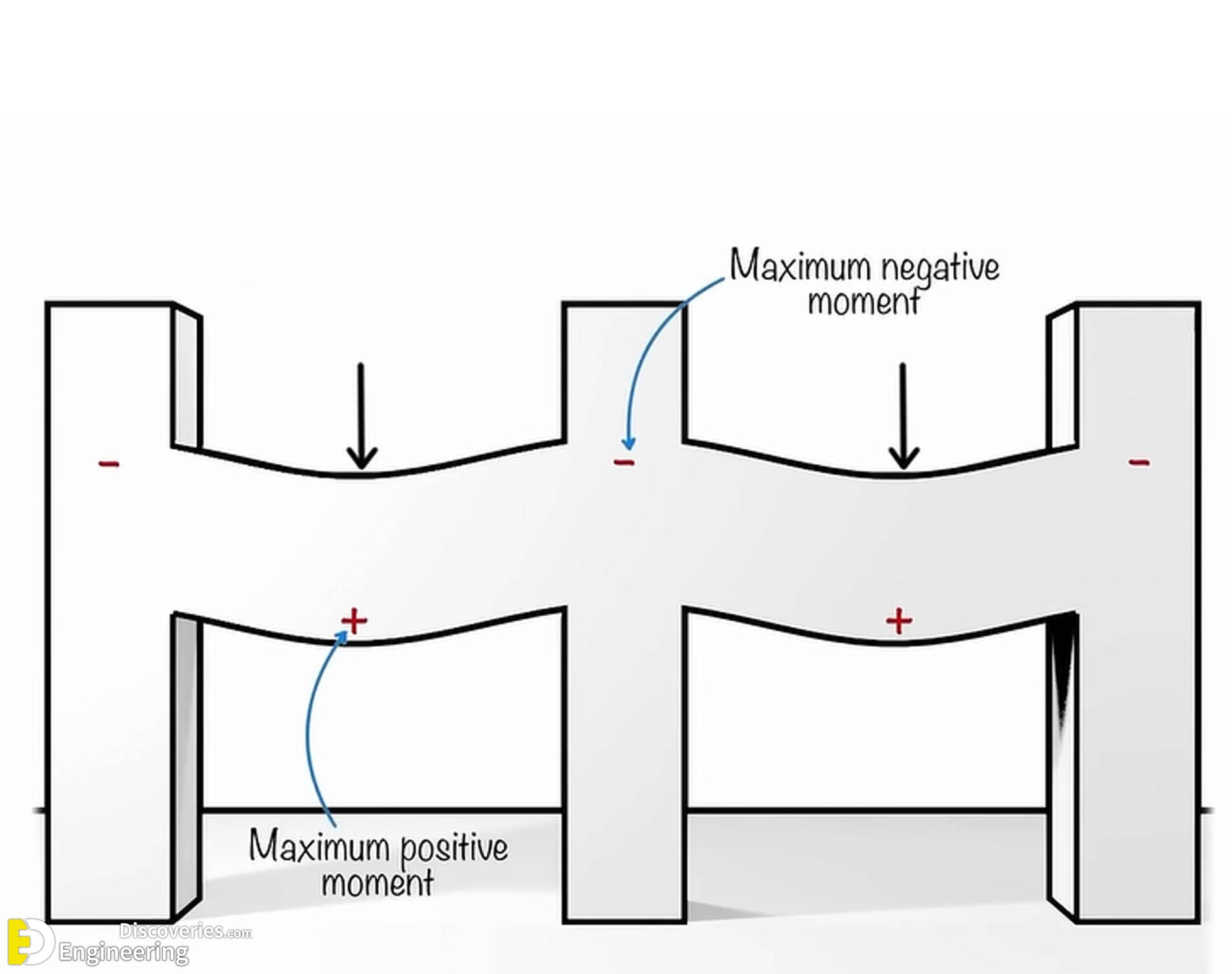
A continuous beam spans over more than two supports, leading to the development of positive and negative bending moments. At the mid-span between supports, positive bending moments dominate, while at the supports, negative bending moments are significant due to hogging behavior.
In simple terms:
Positive Moments (Sagging): Occur at the center of spans.
Negative Moments (Hogging): Occur over the supports.
These variations in moment zones directly affect how reinforcements should be lapped, making strategic positioning crucial.
What is Lapping in Reinforcement?
Lapping is the method of overlapping two rebars to ensure continuity of reinforcement when the desired length is unavailable. It is commonly used when bars need to be extended.
The Indian Standard IS 456:2000 provides guidelines for the lap length, based on:
Type of stress (tension or compression)
Grade of steel
Diameter of bar
Concrete strength
But, while the IS Code provides the dimensions, it does not explicitly state where to lap — and that is where most site-level mistakes happen.
Common Mistakes in Lapping Zones
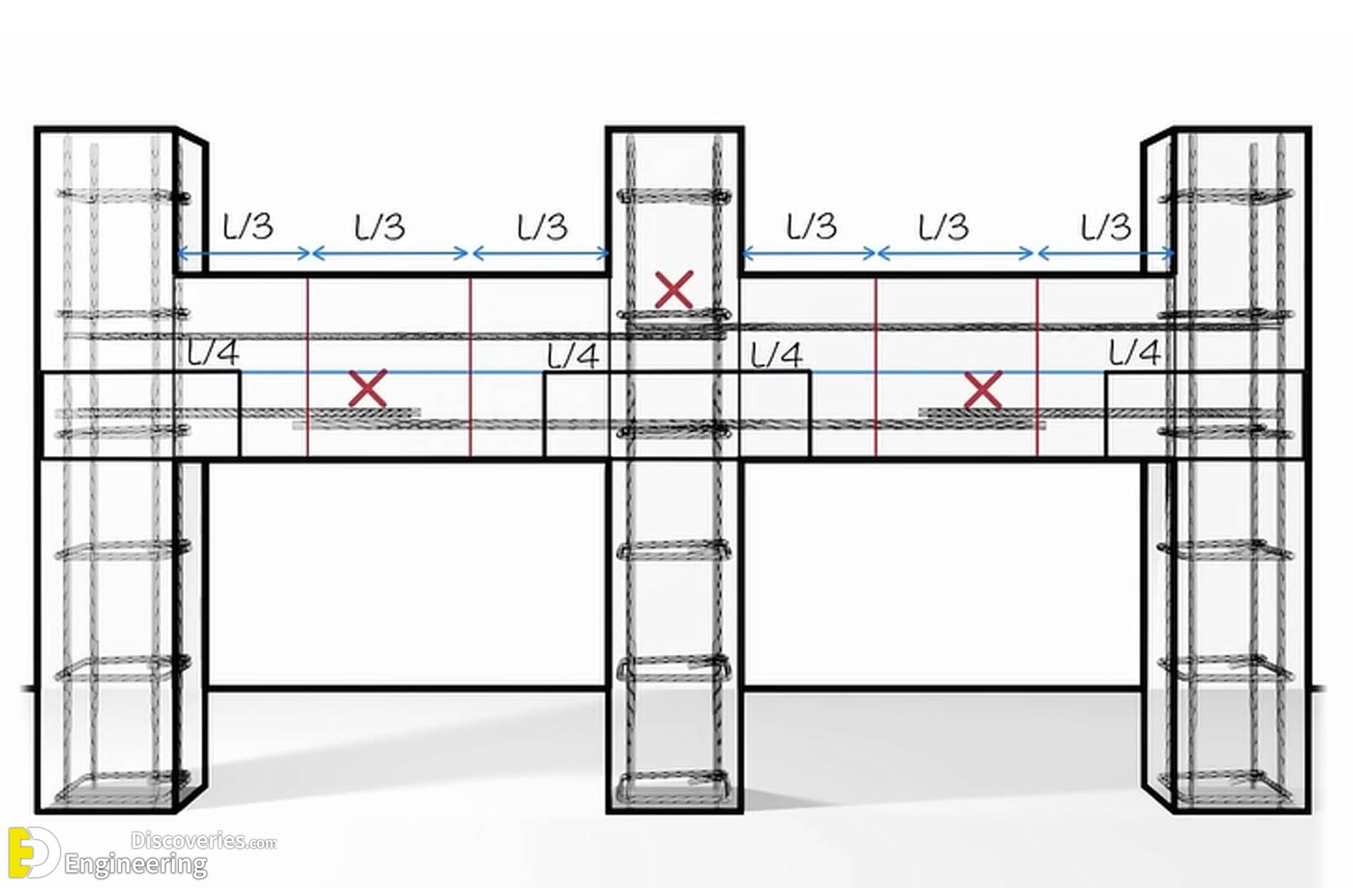
As illustrated in diagram, a major error in construction is lapping bars in regions of high moment. Specifically:
At supports (columns): Where negative moments are maximum.
At mid-spans: Where positive moments peak.
Lapping in these high-stress zones can compromise the ductility, flexural strength, and integrity of the beam.
These errors are often the result of poor site supervision or misinterpretation of structural drawings.
Best Practices for Lapping Zones in Continuous Beams
1. Lap Bars in Low-Stress Zones
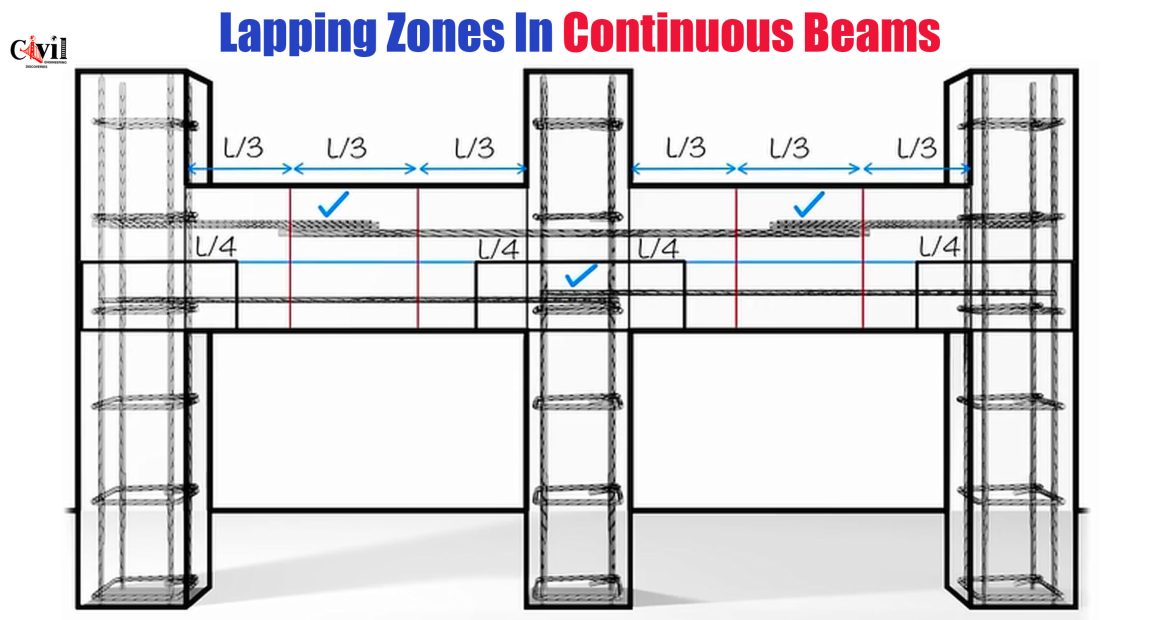
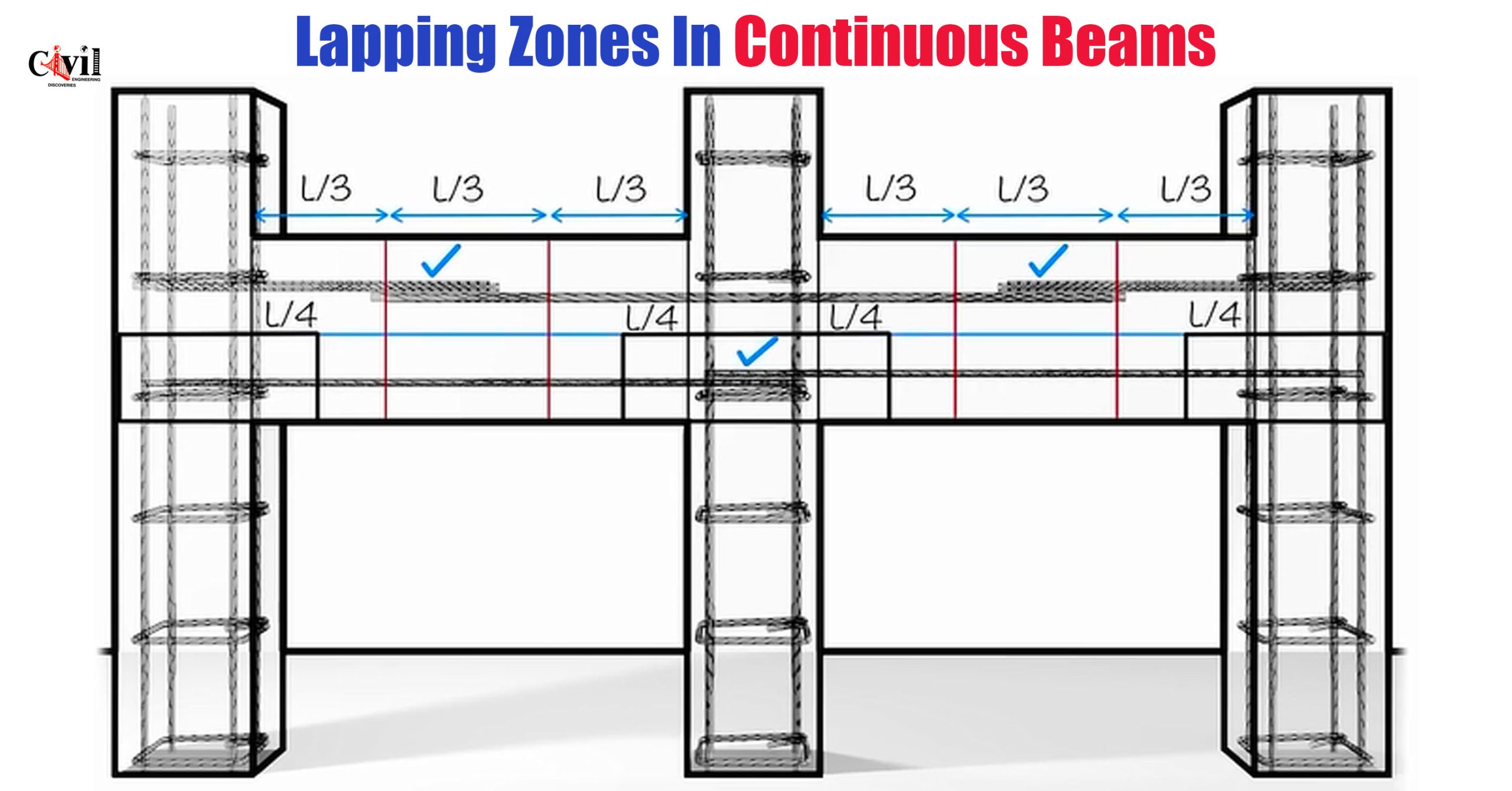
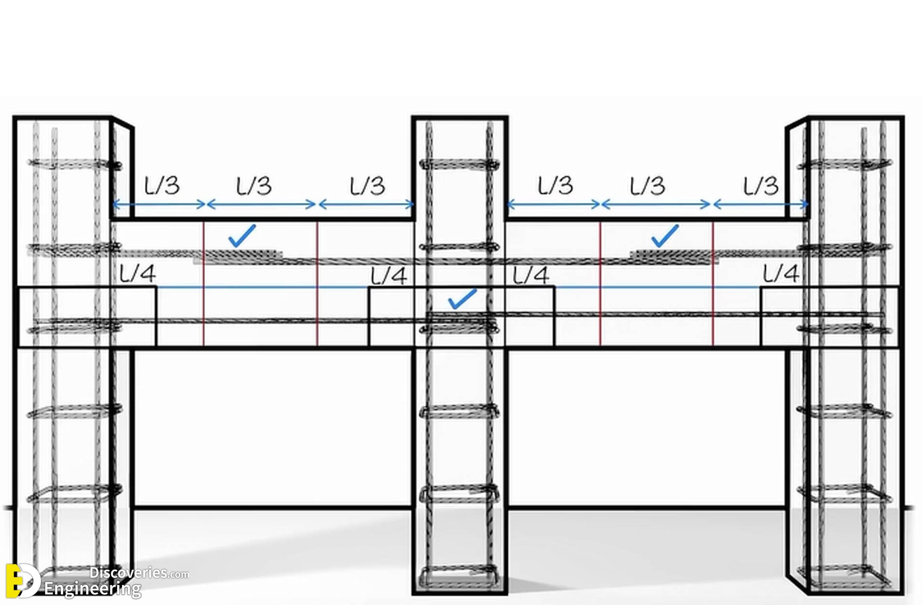
The safest location to lap reinforcement is in regions where the bending moment is close to zero, known as points of contraflexure. These occur:
Around L/3 from each support for the top reinforcement
Around L/4 from each support for the bottom reinforcement
Where:
L = Clear span of the beam between supports
This strategy is shown clearly in the bottom image, where check marks indicate proper placement.
2. Separate Laps for Top and Bottom Bars
Top bars (handling negative moments): Should be lapped away from the support but not near mid-span.
Bottom bars (handling positive moments): Should be lapped away from mid-span but not too close to supports.
3. Stagger Laps to Avoid Weak Planes
Lapping all bars at the same location can create a plane of weakness in the beam. To mitigate this:
Stagger the lap locations by at least 600 mm or 1.3 times the lap length.
Ensure no more than 50% of bars are lapped in the same section.
4. Maintain Proper Lap Length
The lap length should not be random. As per IS 456:2000:
In tension zones: Ld or 30d, whichever is greater
In compression zones: 24d
Where:
d = Diameter of the bar
Ld = Development length based on bond strength
5. Use of Couplers or Welded Splices
For congested or high-stress areas where lapping is unavoidable:
Mechanical couplers provide an alternative with higher reliability.
Welded splices are rarely preferred unless approved by structural consultants.
IS Code Recommendations on Lap Placement
Though the IS 456:2000 doesn’t mandate lap placement zones, the implied practices from its clauses on development length (Clause 26.2.1) and anchorage (Clause 26.2.5) guide the placement indirectly:
Ensure that the lap zone has sufficient concrete cover and confinement.
Avoid placing laps in zones of high stress concentration.
Refer also to SP 34 (Handbook on Reinforcement and Detailing), which visually demonstrates appropriate lap zones in continuous beams.
Practical Site-Level Tips
Mark lap zones clearly in reinforcement drawings using color-coded bar bending schedules (BBS).
Instruct bar benders to strictly follow the designated zones.
Conduct random checks during concrete casting to verify compliance.
Use tie wires effectively to prevent slippage of lapped bars during concrete pouring.
For long beams, consider alternating lapping patterns to preserve uniformity.
Advantages of Proper Lap Placement
Enhanced Structural Strength: Lapping in low-stress areas ensures better transfer of tensile/compressive forces.
Long-Term Durability: Avoiding stress zones prevents early cracking and reinforcement corrosion.
Better Load Distribution: Reinforcement acts monolithically with concrete, sharing loads evenly.
Economical Construction: Avoids wastage from unnecessary rebar overlaps or failures.
Summary: Do’s and Don’ts of Lapping in Continuous Beams
| Practice | Recommended? | Reason |
|---|---|---|
| Lapping at support (top bars) | ❌ No | High negative moments – weak joint |
| Lapping at mid-span (bottom bars) | ❌ No | High positive moments – risk of failure |
| Lapping at L/3 (top bars) | ✅ Yes | Near zero moment – ideal zone |
| Lapping at L/4 (bottom bars) | ✅ Yes | Minimum stress – safe for load transfer |
| Staggering laps | ✅ Yes | Prevents plane of weakness |
| Lapping more than 50% at once | ❌ No | Concentrated stress – risk of crack |
Click Here To Steel Bars Over-Lap Formulas Used In Column, Slab And Beams
