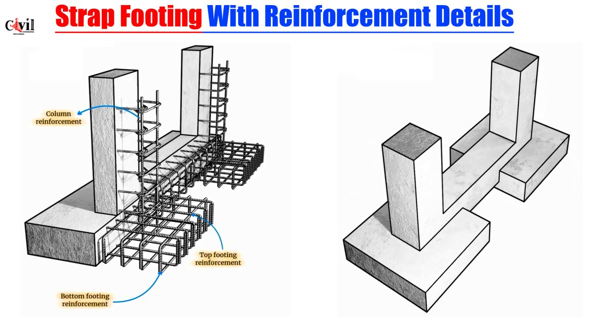
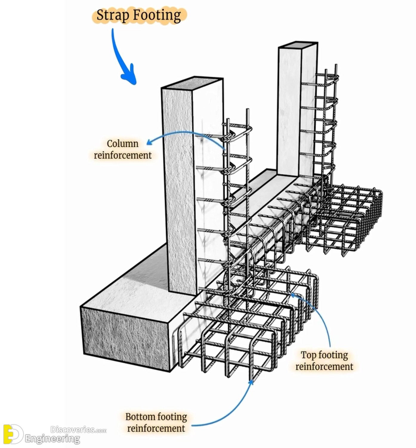
Strap footing, a specialized type of combined footing, is critical in supporting adjacent columns where space or load distribution makes isolated footings impractical. This structural element connects two or more footings via a strap beam, ensuring that the foundation distributes loads uniformly and maintains balance, especially where eccentric loads exist. Below, we delve deeply into the structural logic, reinforcement layout, and design considerations of strap footings with precise reinforcement detailing.
What Is Strap Footing?
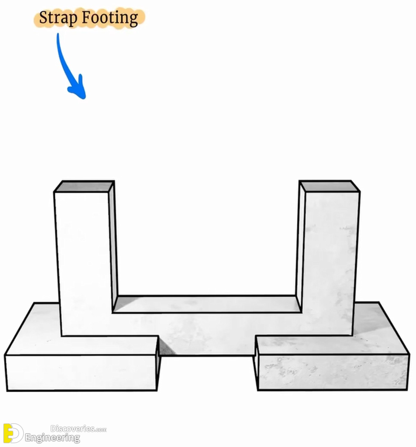
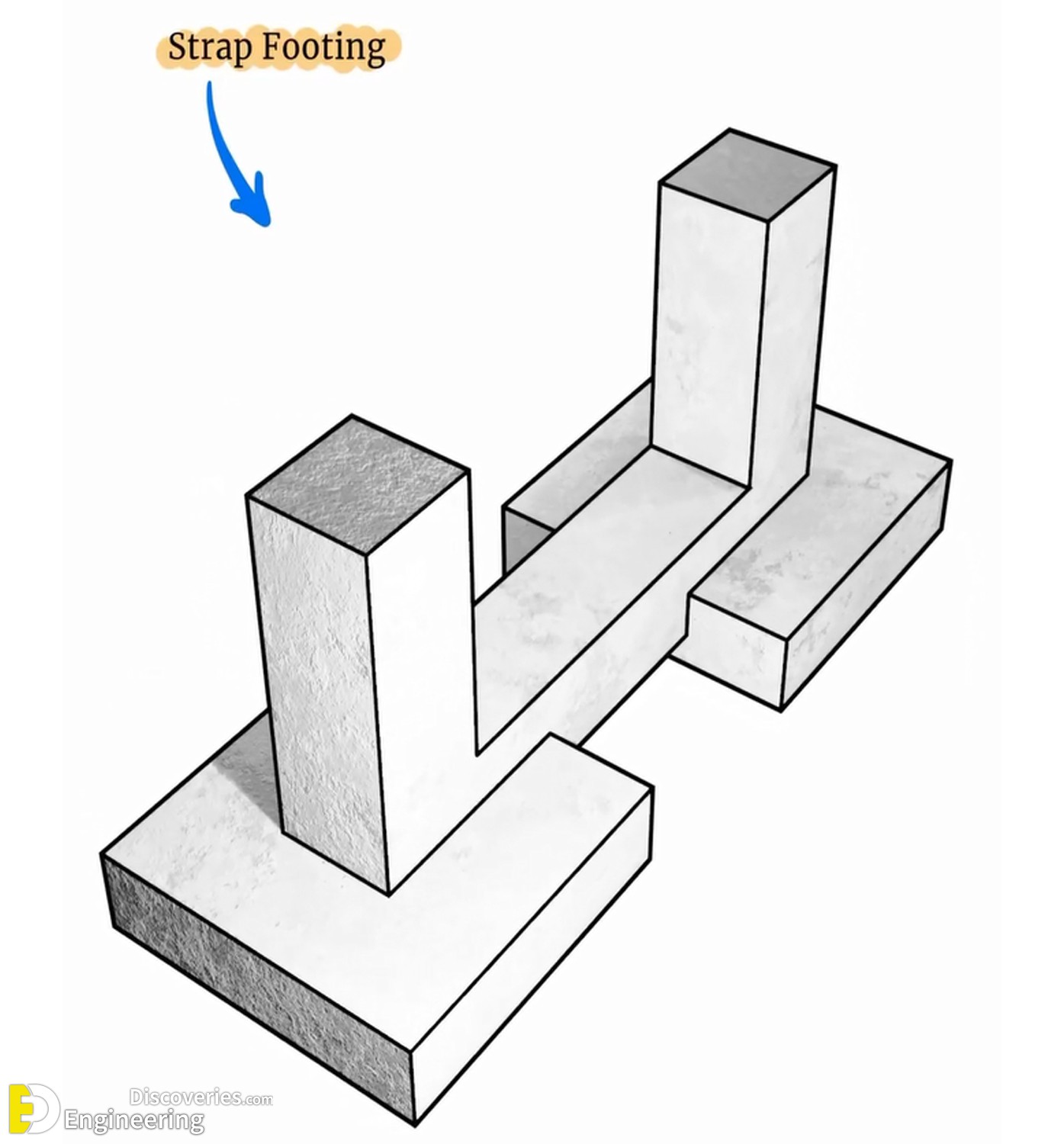
Strap footing, also known as cantilever footing, is used when two columns are placed too close for isolated footings or when one column is near a property line, restricting the foundation’s extension. The strap beam connects the footings and helps transfer the unbalanced moment to the other footing, preventing differential settlement and maintaining structural integrity.
This method avoids using a raft foundation, offering a cost-effective yet robust alternative in specific situations.
Key Components of Strap Footing
To understand strap footing thoroughly, we must break it into its key structural components:
1. Footings
Each column rests on an individual footing slab that bears the load directly to the soil. These footings are rectangular or square, depending on column dimensions and soil bearing capacity.
2. Strap Beam
The strap beam is the connecting member that links two footings, transferring load from the eccentrically loaded column to the centrally loaded footing. It does not bear directly on the soil and is designed to be rigid.
3. Columns
The reinforced concrete columns transmit vertical loads from the superstructure down to the foundation through the footings.
Structural Behavior of Strap Footing
The load transfer mechanism of strap footings involves a combination of direct bearing pressure under the footings and a balancing moment created by the strap beam. When an exterior column sits near the property boundary, its footing cannot be centrally located under the column. The strap beam connects it to an interior footing, redistributing the moment caused by eccentricity.
This system helps:
Reduce the tilting of columns
Prevent differential settlement
Maintain vertical alignment
Reinforcement Details in Strap Footing
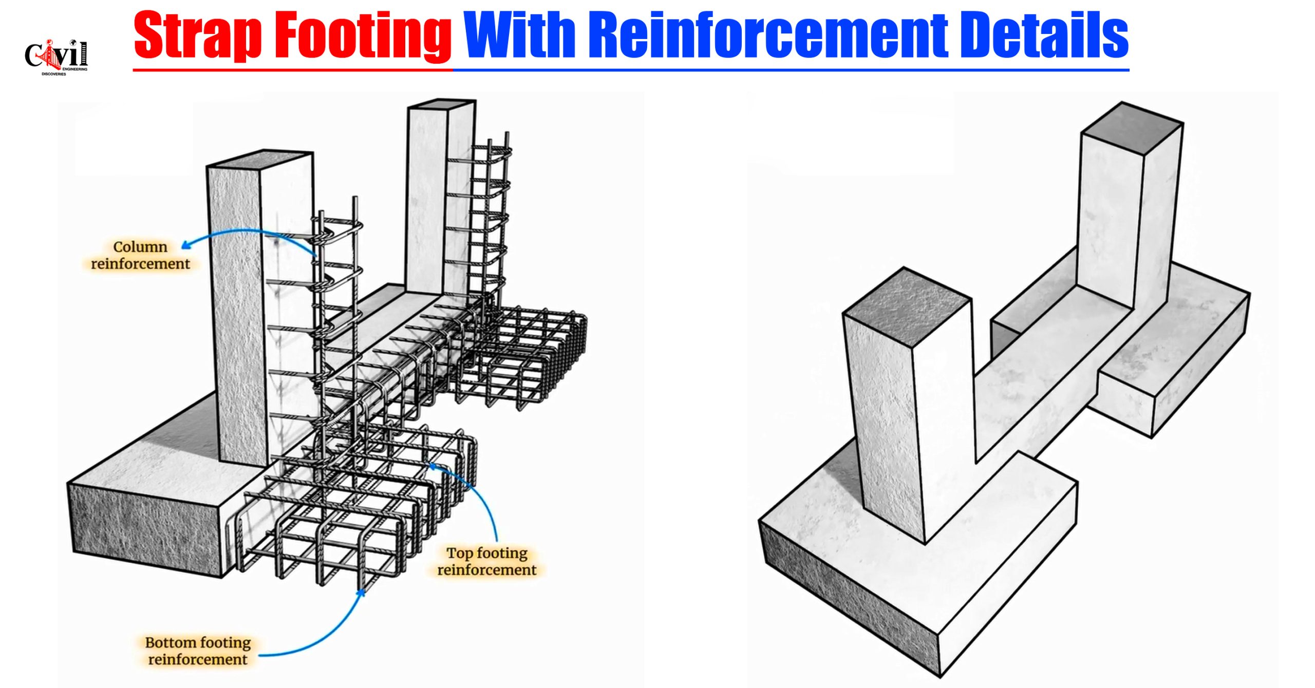
Proper reinforcement ensures structural performance and durability under applied loads. The key reinforcement elements include:
1. Column Reinforcement
Vertical bars and ties form the reinforcement cage inside columns. High-tensile steel bars resist axial and bending stresses. Ties hold the verticals in place and improve seismic resistance.
2. Bottom Footing Reinforcement
The bottom layer of the footing slab comprises main reinforcement bars placed perpendicular to the longer span of the footing. These bars handle bending moments and are anchored properly into the concrete.
Bar Spacing: Typically 100–200 mm c/c
Bar Diameter: Depends on structural load (commonly 12mm–20mm)
3. Top Footing Reinforcement
Placed in the top layer of the footing, this reinforcement resists upward forces and secondary bending moments. This is crucial in strap footings due to the combined stress from the beam action.
Top bars are essential near the strap beam’s ends and above the column-footing junction.
4. Strap Beam Reinforcement
The strap beam behaves like a deep beam or cantilever between footings. It is reinforced heavily due to:
High bending moments
Shear forces
Torsional effects
Longitudinal reinforcement resists bending, while stirrups handle shear and ensure ductility.
Top and Bottom Bars: Provided for negative and positive moments
Stirrups: Usually 8mm–12mm diameter @ 150 mm c/c spacing
Design Considerations for Strap Footing
1. Load Distribution
Load on each column, both vertical and horizontal, must be calculated precisely. These include:
Dead loads
Live loads
Seismic and wind loads
2. Soil Bearing Capacity
The allowable soil bearing capacity must be assessed via geotechnical investigations. Strap footing is ideal when the soil is moderately firm and well-draining.
3. Strap Beam Design
The strap beam must be designed to carry bending and shear forces without undergoing excessive deformation. It is usually kept above the footing and not in contact with soil, to reduce friction and increase beam action.
4. Reinforcement Anchorage
Proper anchorage and development length must be ensured, especially where the strap beam connects to footings and columns. Hooks or bends are incorporated as per design codes.
Advantages of Strap Footing
Economical alternative to raft or mat foundations in tight spaces
Effective load transfer for eccentrically loaded columns
Prevents tilting of isolated footings near boundaries
Reduces excavation area compared to spread footings
Improves foundation behavior in non-uniform soil conditions
Construction Tips for Strap Footing
Ensure precise formwork and leveling for strap beams.
Use high-quality concrete mix, preferably with additives for improved workability.
Install cover blocks to maintain proper reinforcement cover.
Use vibrators to eliminate air pockets during concrete pouring.
Allow sufficient curing time to achieve the desired strength.
Common Mistakes to Avoid
Incorrect bar placement, especially at junctions of the strap beam and column.
Insufficient anchorage leading to slippage under load.
Omitting top reinforcement is critical for moment resistance.
Improper beam alignment reduces its effectiveness in balancing the moment.
Not considering uplift pressure if the beam bears on expansive soil.
Code References and Standards
For the design of strap footings, refer to:
IS 456:2000 – Indian Standard for Plain and Reinforced Concrete
ACI 318 – Building Code Requirements for Structural Concrete
BS 8110 – Structural Use of Concrete
Eurocode 2 – Design of Concrete Structures
Click Here To See Learn The Reinforcement Details Of Beam-Column Junctions Using L Bars!
