
Introduction
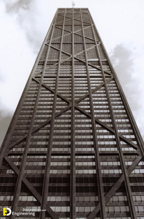
A braced frame is a structural system commonly used in structures subject to lateral loads such as wind and seismic pressure. The members in a braced frame are generally made of structural steel, which can work effectively both in tension and compression. The beams and columns that form the frame carry vertical loads and the bracing system carries the lateral loads.
Bracing systems
Both systems can significantly reduce the buckling capacity of the compression brace so that it is less than the tension yield capacity of the tension brace. This can mean that when the braces reach their resistance capacity, the load must instead be resisted in the bending of the horizontal member.
1- Vertical bracing
Bracing between column lines provides load paths for the transference of horizontal forces to ground level. Framed buildings required at least three planes of vertical bracing to brace both directions in plan and to resist torsion about a vertical axis.
2- Horizontal bracing system
The bracing at each floor level provides load paths for the transference of horizontal forces to the planes of vertical bracing. Horizontal bracing is needed at each floor level, however, the floor system itself may provide sufficient resistance. Roofs may require bracing.
Types of bracing
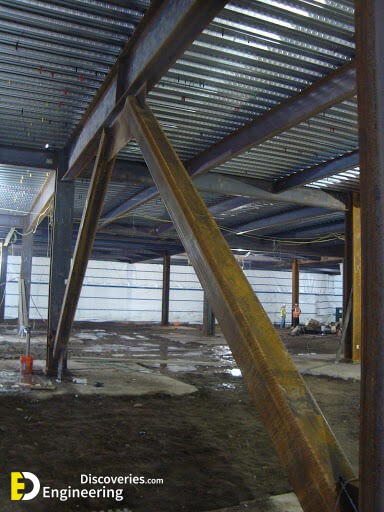
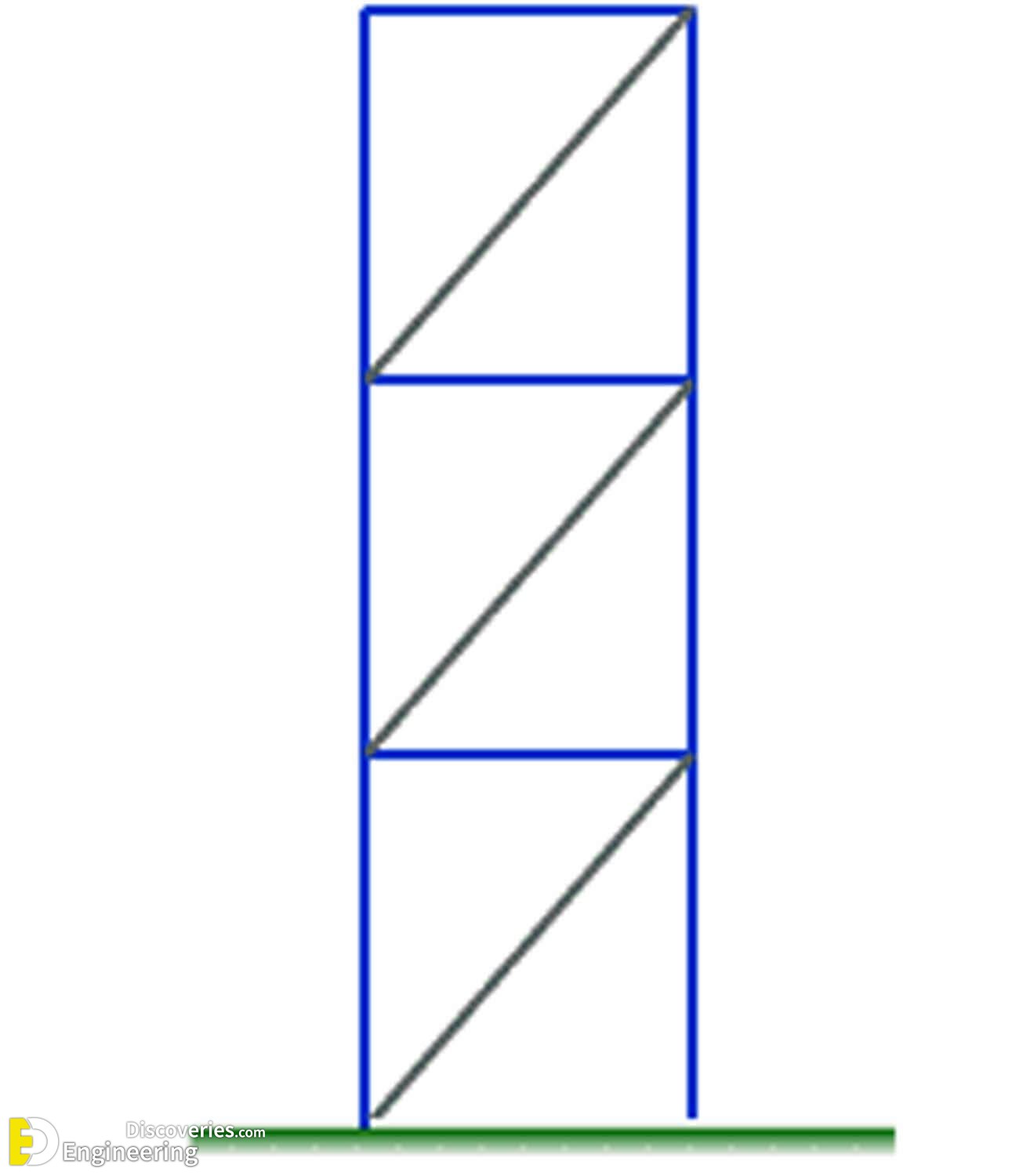
Single diagonals
Trussing, or triangulation, is formed by inserting diagonal structural members into rectangular areas of a structural frame, helping to stabilise the frame. If a single brace is used, it must be sufficiently resistant to tension and compression.
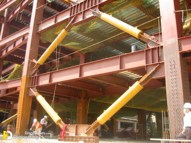
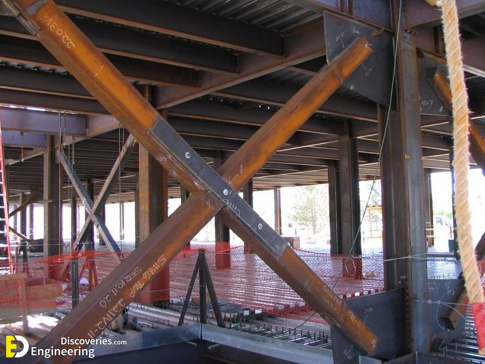
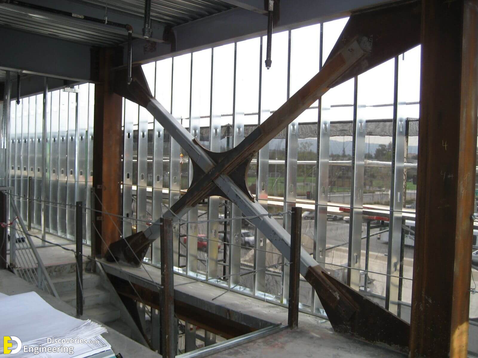
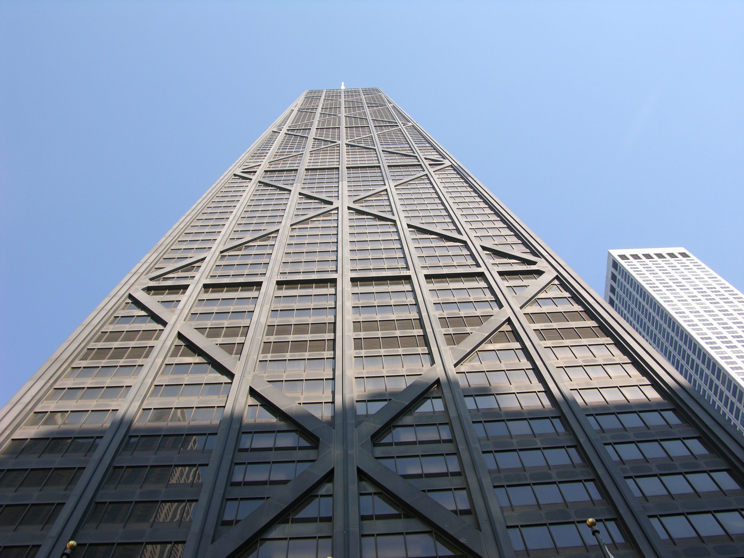
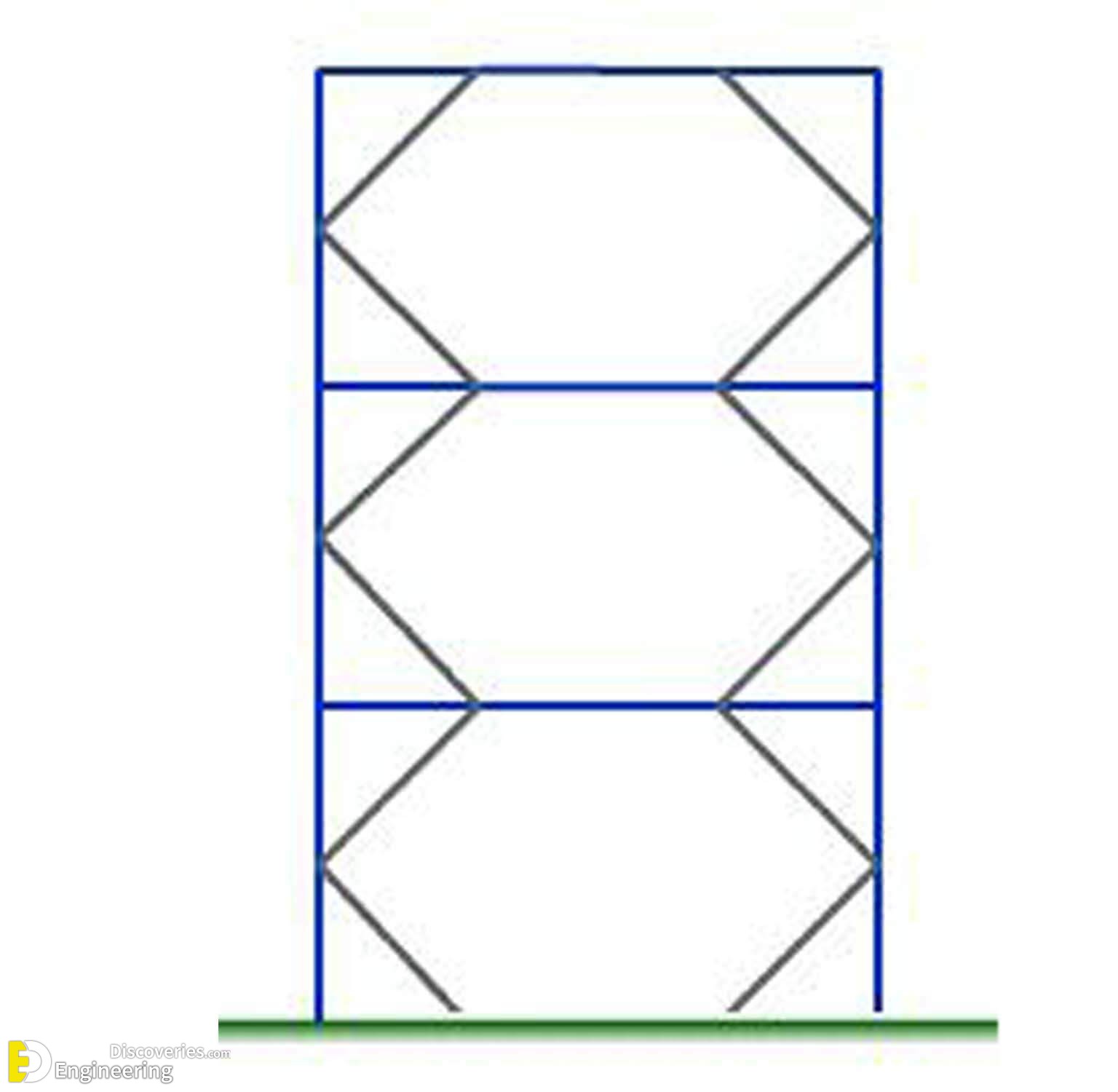
Cross-bracing
Cross-bracing (or X-bracing) uses two diagonal members crossing each other. These only need to be resistant to tension, one brace at a time acting to resist sideways forces, depending on the direction of loading. As a result, steel cables can also be used for cross-bracing. However, cross bracing on the outside face of a building can interfere with the positioning and functioning of window openings. It also results in greater bending in floor beams.
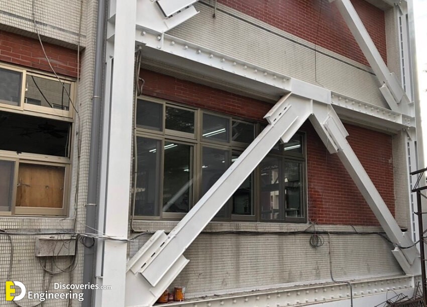
K-bracing
K-braces connect to the columns at mid-height. This frame has more flexibility for the provision of openings in the facade and results in the least bending in floor beams. K-bracing is generally discouraged in seismic regions because of the potential for column failure if the compression brace buckles.
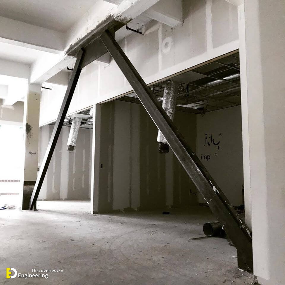
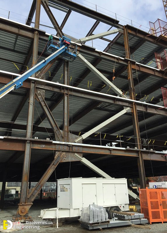
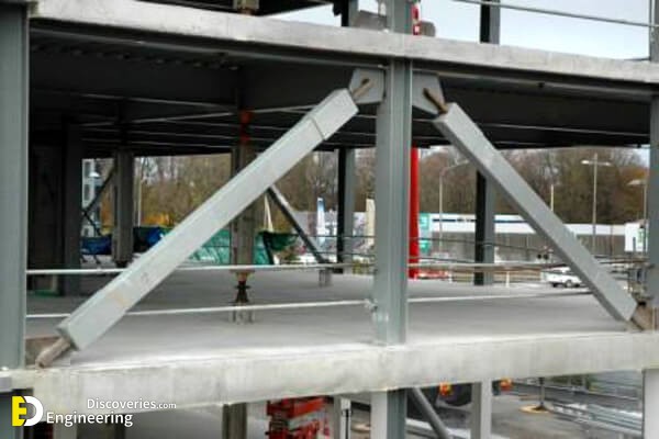
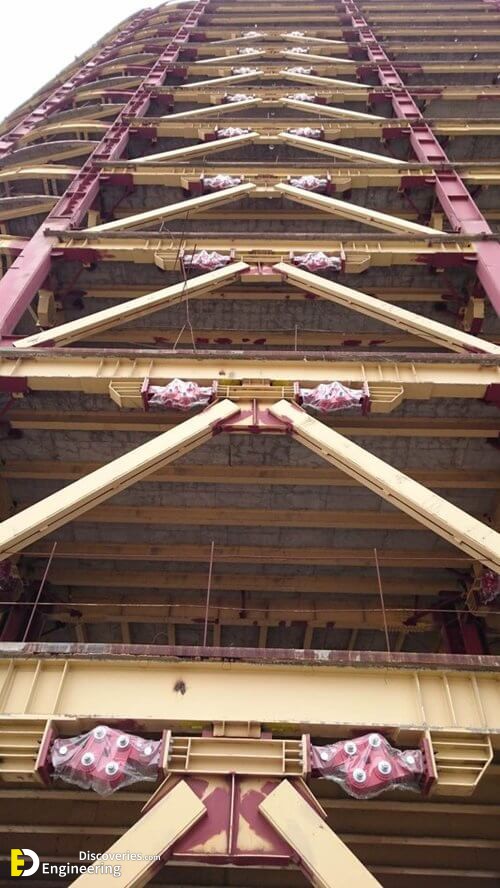
V-bracing
Two diagonal members forming a V-shape extend downwards from the top two corners of a horizontal member and meet at a centre point on the lower horizontal member (left-hand diagram). Inverted V-bracing (right-hand diagram, also known as chevron bracing) involves the two members meeting at a centre point on the upper horizontal member.
Click Here To See Terminology Of Steel Design
Loading related articles...
Loading recent articles...
Loading featured articles...
