
Shear force is a fundamental concept in structural engineering that plays a critical role in the design and analysis of various structures, particularly beams and columns. It represents the internal forces that act parallel to the cross-section of a structural member, essentially trying to slice or shear the member. A thorough understanding of shear forces is paramount for ensuring the safety and stability of structures, as unchecked shear can lead to catastrophic failures.
This comprehensive article delves into the intricacies of shear forces, covering their definition, types, calculation, and representation through shear force diagrams. Furthermore, it explores the closely related concept of shear stress, its distribution within structural elements, and the crucial design considerations to mitigate shear-related failures in both concrete and steel structures.
What are Shear Forces?
In the realm of structural engineering, a shear force is an internal resisting force that is generated in a structural member to counteract the effect of externally applied transverse loads. These external loads, which are applied perpendicular to the longitudinal axis of the member, create a tendency for one part of the member to slide vertically relative to an adjacent part. The internal shear force is the force that resists this sliding motion.
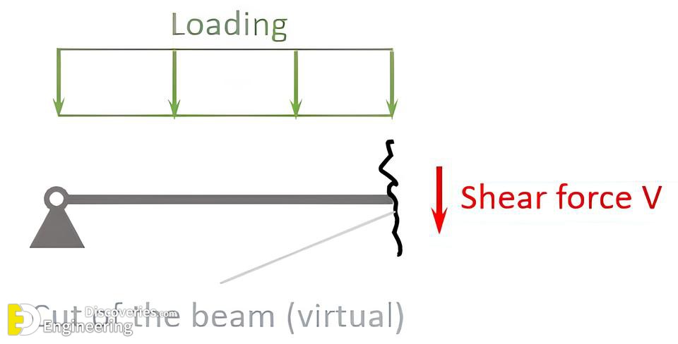
Imagine a wooden plank supported at both ends with a heavy weight placed in the middle. The weight pushes the central part of the plank downwards, while the supports push the ends upwards. This creates opposing vertical forces. If you were to make an imaginary vertical cut through the plank at any point, you would find that to maintain equilibrium, there must be an internal force acting parallel to that cut. This internal force is the shear force.
The standard unit for shear force is the Newton (N) in the International System of Units (SI).
Types of Internal Forces
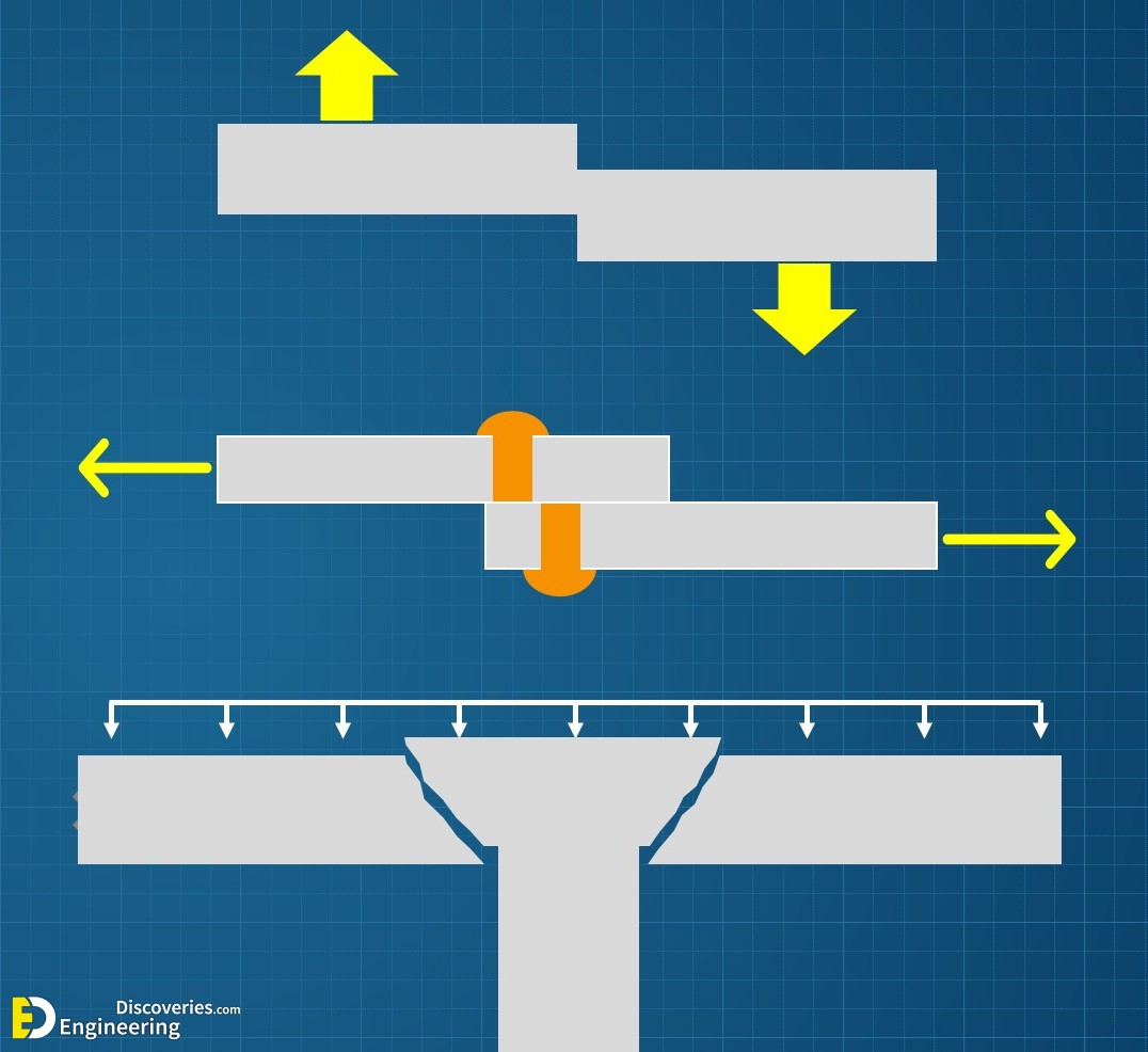
When a structural member is subjected to external loads, three types of internal forces are generally developed at any given cross-section:
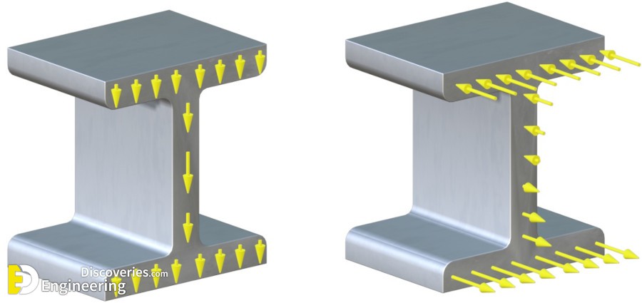
Shear (left) and normal (right) internal forces
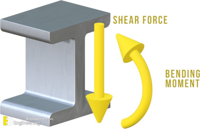
The effect of the internal forces on the beam cross-section can be represented by two resultants – a shear force and a bending moment
While all three are important, this article will focus primarily on the shear force.
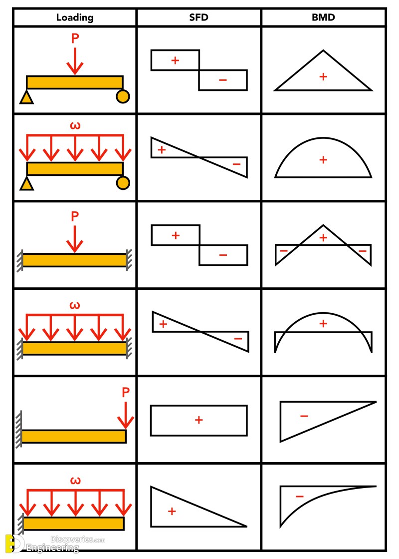
Shear Force Diagrams: Visualizing Internal Forces
A Shear Force Diagram (SFD) is a graphical representation of the variation of the shear force along the length of a structural member. It is an indispensable tool for structural engineers as it helps to:
Constructing a Shear Force Diagram: A Step-by-Step Approach
The process of drawing a shear force diagram generally involves the following steps:
Calculating Shear Force
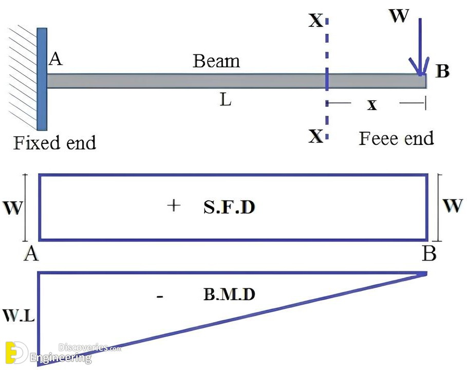
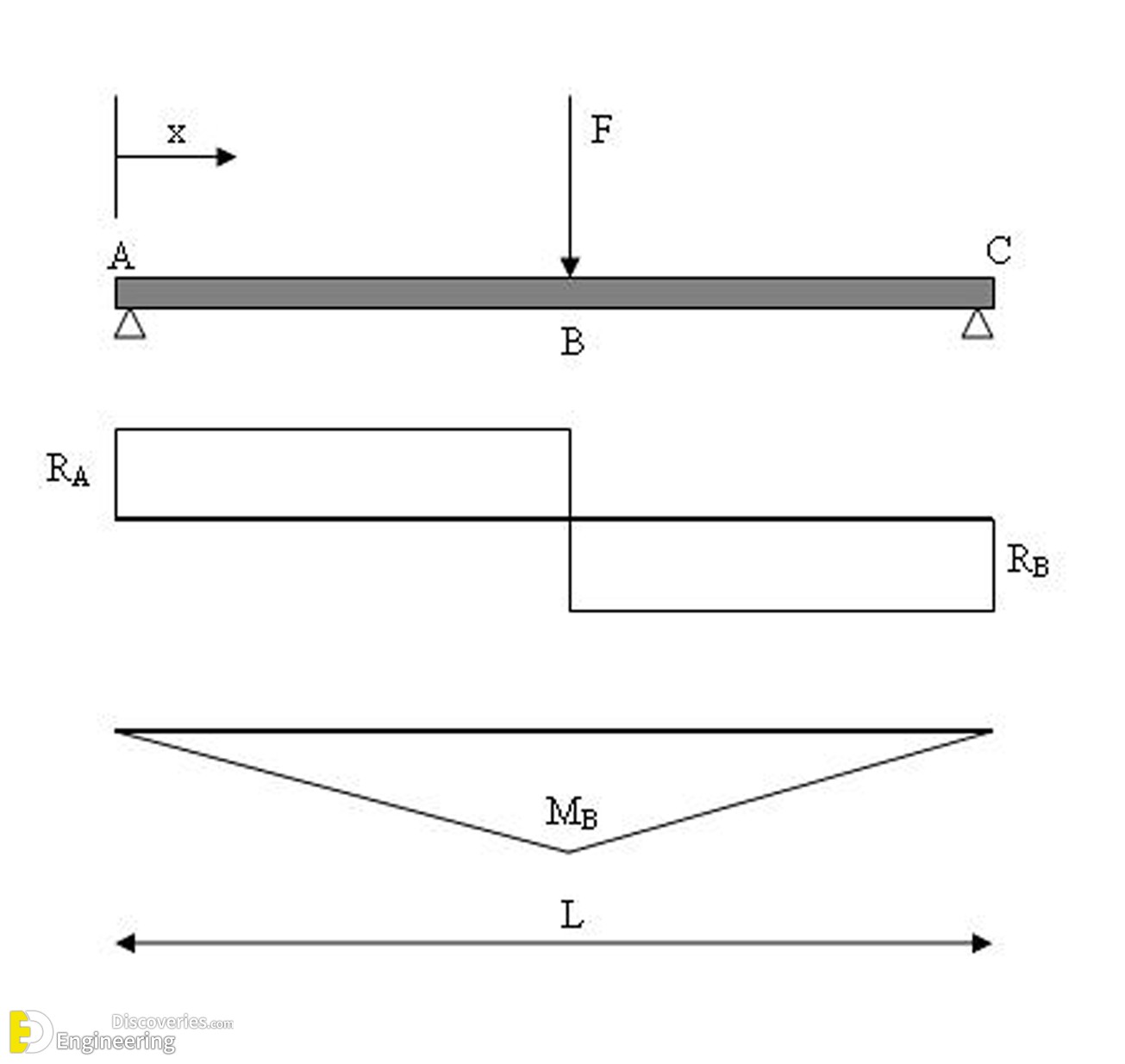
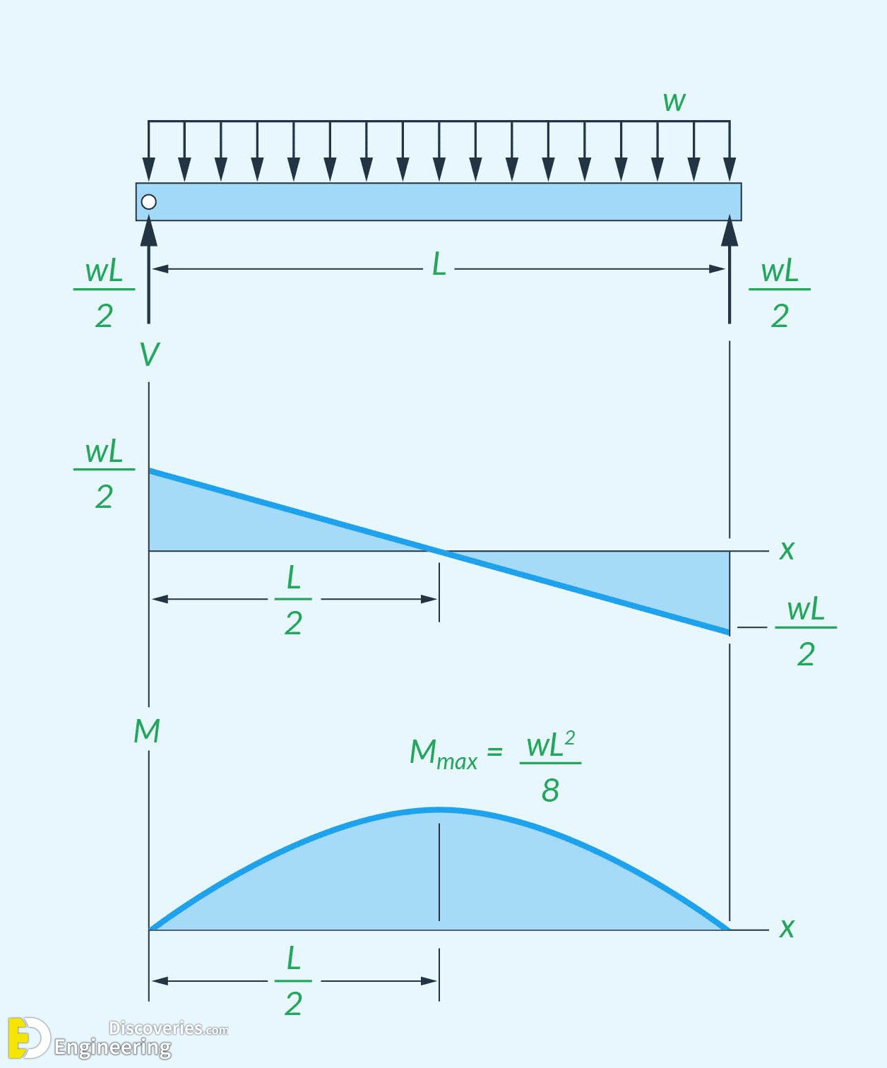
The calculation of shear force at any point ‘x’ along a beam can be determined by taking the algebraic sum of all the vertical forces acting on one side (either left or right) of that point.
Examples of Shear Force Calculation:
The Relationship Between Shear Force and Shear Stress
While shear force represents the total internal force acting on a cross-section, shear stress (τ) is the intensity of this force distributed over the area of the cross-section. The relationship is given by the formula:
Where:
However, the distribution of shear stress across a beam’s cross-section is not uniform.
Shear Stress Distribution in Beams
The shear stress is zero at the extreme top and bottom fibers of the beam and is maximum at the neutral axis (the horizontal plane passing through the centroid of the cross-section).
Shear Failure and Design Considerations
Excessive shear forces can lead to shear failure, which is often a sudden and brittle failure, making it a critical consideration in structural design.
Shear Failure in Concrete Beams
Concrete is strong in compression but weak in tension. Shear forces induce diagonal tension stresses in a beam. If these stresses exceed the tensile strength of the concrete, diagonal cracks will form, leading to a shear failure.
To prevent this, shear reinforcement, typically in the form of vertical or inclined stirrups (steel bars), is provided. These stirrups are designed to resist the diagonal tension and carry the shear forces across the potential crack planes. The design for shear in reinforced concrete beams involves calculating the shear capacity of the concrete itself and then providing sufficient shear reinforcement to carry the remaining shear force.
Shear Failure in Steel Beams
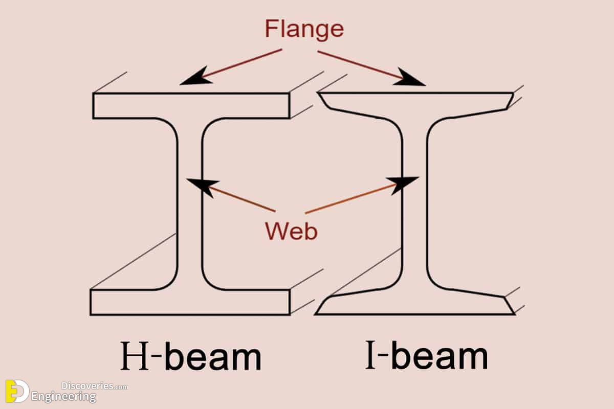
In steel beams, shear failure can occur in the web of the beam. This can manifest as:
The design of steel beams for shear involves checking the shear capacity of the web against both yielding and buckling. If the web is too slender, stiffeners may be required to prevent buckling.
Click Here To See Understanding Internal Forces In Structural Elements
Loading related articles...
Loading recent articles...
Loading featured articles...
