
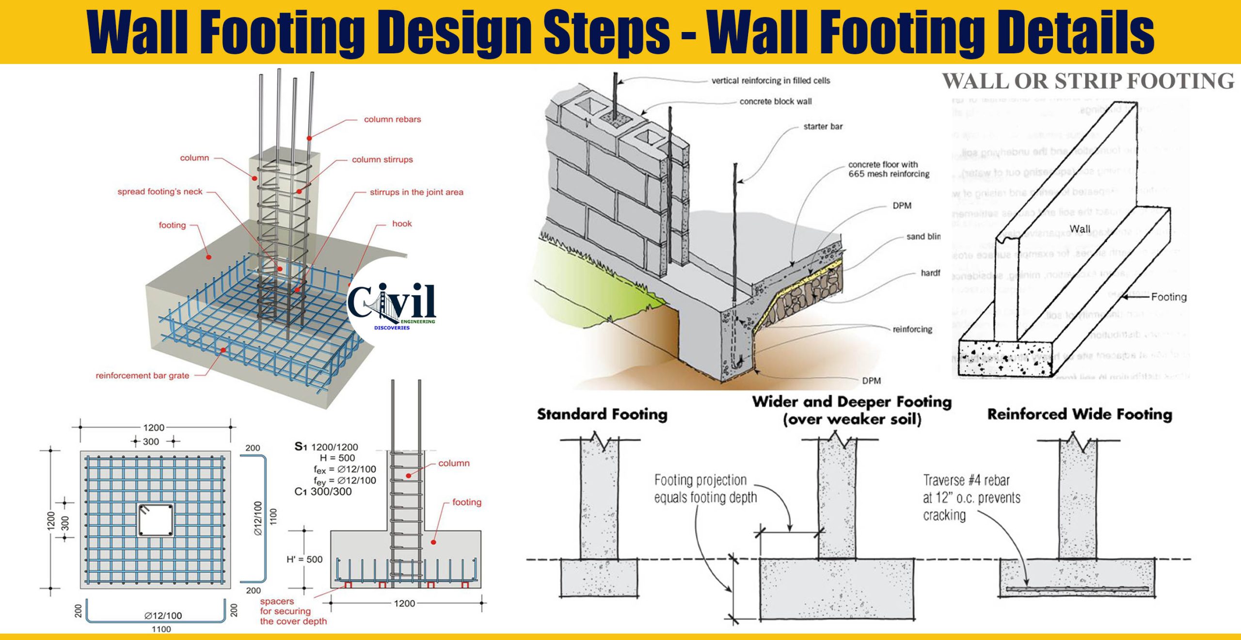
Wall footing design is carried out with some assumptions that should be considered while designing. The first assumption is to consider that soil pressure is distributed linearly throughout. This can only be achieved when resultant of soil pressure coincides with the results of soil force. Because of this rotation of footing can be avoided. Generally, footings are designed by following the strength design method.
Wall footing design example statement
A 10” thick wall carries a service a dead load of 8k/ft and service live load of 9k/ft. At the base of footing, the allowable soil pressure is 5000psf and base of footing is 5’ below the existing ground surface. Now your task is to design the wall footing for;
Concrete compressive strength= f’c = 3ksi
Yield strength of steel = fy = 60ksi.
Soil density = 120lb/ft3.
Solution
Note: Usually low strength of concrete in footing is used then that in columns. It requires the use of dowel to accommodate this strength change.
Step 1: Estimate the size of footing and factor net pressure
While designing wall footing, normally one feet strip of the wall and footing is considered for the sake of easiness in the calculation. The allowable soil pressure is 5ksf. The allowable net soil pressure will be 5ksf. Since the thickness of footing is not known at this stage a suitable thickness of footing equal to (1-1.5)x The wall thickness can be assumed.
1.5 x 9’’ = 13.5’’ take 13’’
Step 2: Find the allowable soil pressure
qn=5−[(1.083times0.150)+(5−1.083)times0.120]
[q_{n}=4.367 ksf] [Area-of-footing=frac{8+9}{4.3676}]Try 47’’ (3.91’) Wide footing
Factored Net Pressure = qnet = 6.138ksf
Step 3: Check the adequacy of footing depth against shear
Only one-way shear or beam shear is significant in-wall footings. The critical section for this type of shear is at distance‘d’ from the face of the wall. Where ‘d’ is the effective depth of footing.
Assuming that we shall use #4 bar.
d = 13 – 3 – ¼ = 9.75″
The Tributary area for one way shear
Tributary area = Shaded area for one way shear
D = H – CLEAR COVER – 1/2 BAR DIAMETER
d = 13 – 3 -1/4
d = 9.75″
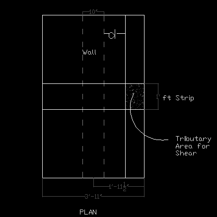
Tributary−Area=frac8.75X112=0.729ft2
Vu = qnu X Tributary Area = 6.138 X 0.729 = 4.475 k/ft
Shear capacity
Shear−Capacity=ovctimes2timessqrtf′ctimesbwd
[Shear-Capacity = 0.75times 2timessqrt{3000}times 2timesfrac{9.75}{1000}]Shear Capacity = 9.618k/ft > Vu → Footing is ok against one-way shear
Step 4: Design reinforcement for the moment
The critical section for the moment is the face of the wall. Hence, the moment is maximum at the face of the wall. Therefore, we will find the moment at that point and then a reinforcement required to cater to this moment.
Tributary area for flexure
Tributary−Area=(frac9.75”+8.75”12)times1‘=1.54fracft2ft
[M_{u}=q_{nu}timesfrac{l^{2}}{2}]
Mu=6.138timesfrac1.5422=7.294kfracftft
Area of steel per foot
Mu=oMn→
Mu=oAsfytimes0.9d
→Footings are generally reinforced structure, so jd can be taken as 0.9d.
7.294times12000=0.9timesAstimes60,000times(0.9times9.75)→
As=0.184fracin2ft
Now compare it with this Area of steel corresponding to ρmin
ρmin = Temperature and Shrinkage reinforcement
ρ = 0.0018 for Grade 60 steel
(As)min=rhomintimesbtimesh
[(A_{s})_{min}=0.0018times 12times 13 ](As)min=0.2808fracin2ft
ρmin governs. Hence, provide area equal toρmin reinforcement 0.2808 square inch per feet.
Provide #4 @ 81/2″ C/C
→Maximum Bar spacing = 24″ or 18″
Step 5: Check development length
Development length value can be checked from the ACI Code 318-M table A-11. Corresponding to #4 bar and 3000Psi concrete compressive strength. The value of development length is 43.8″.
Find the distance from the mid of the wall to the end of the bar;
Distance = 23.5 – 3 = 20.5″ <21.4″ → Ok
Also, provide hooks at the end of the wall or you can also increase the width of footing. Provide 180° hook.
Similarly, select minimum temperature and shrinkage reinforcement in the other direction.
(As)min=0.2808fracin2ft
Provide #4 @ 8 1/2″ Center to center