In the world of structural engineering and the mechanics of materials, understanding the bending moment diagram (BMD) for different beam configurations is not just critical—it is foundational. One such configuration that often puzzles students and professionals alike is the fixed-pinned beam subjected to a point load.
In this article, we will dissect the problem presented in the image, analyze the structure, and determine which bending moment diagram is correct, with a clear explanation of why it is so.
Understanding the Beam Configuration
The beam in question is:
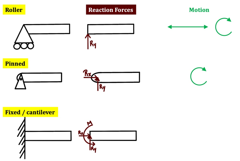
- Fixed at the left end: This means it resists vertical translation, horizontal translation, and rotation.
- Pinned at the right end: This support allows rotation and horizontal displacement resistance but no moment resistance.
- Subjected to a point load P at the center.
This beam is known as a statically indeterminate beam due to the fixed support at one end. However, in many basic analysis problems, it can be assumed that the load is centered and symmetrical to simplify the solution.
Support Reactions and Moment Distribution
Let’s break this down.
Fixed Support (Left)
- Vertical Reaction: Yes
- Horizontal Reaction: Yes (though not critical in this case)
- Moment Reaction: Yes
Pinned Support (Right)
- Vertical Reaction: Yes
- Horizontal Reaction: Yes
- Moment Reaction: No
Due to the fixed support on the left, the beam develops a negative moment at that end. On the other hand, the pinned support on the right does not resist any moment, which means the moment at that end is zero.
Qualitative Shape of the Bending Moment Diagram
For a beam like this, with a central load and a fixed-pinned support configuration, the bending moment diagram will have the following characteristics:
- Maximum negative moment at the fixed end (left).
- Moment gradually decreases toward zero at the pinned end (right).
- The shape of the diagram is triangular, starting from a peak at the fixed support and reducing linearly to zero at the pinned support.
Evaluating the Given Options
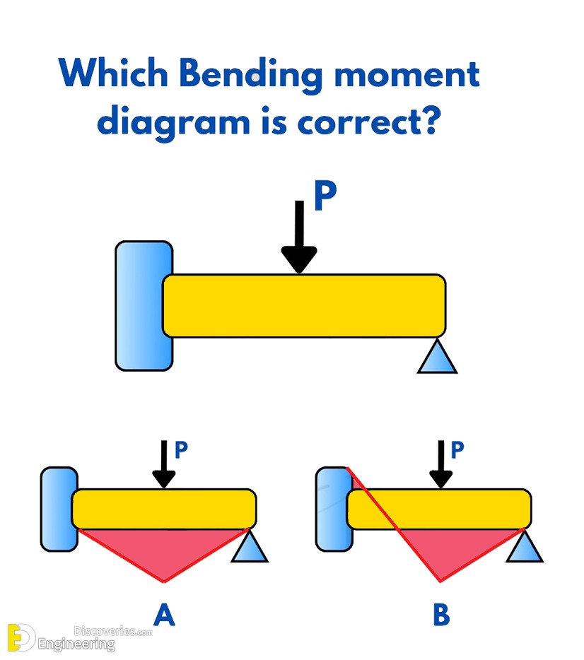
From the image provided, we see two bending moment diagrams labeled:
- Option A: Symmetrical triangle with peak moments at both supports.
- Option B: Moment diagram starts from a peak on the left and tapers to zero on the right.
Now let’s assess:
🔴 Option A – Incorrect
- This shows non-zero moment at the pinned end, which violates the fundamental condition of a pinned support (it cannot resist moment).
- It assumes both supports act like fixed ends, which is structurally inaccurate for this case.
✅ Option B – Correct
- Moment starts high at the fixed end and tapers to zero at the pinned end.
- This perfectly represents the expected behavior of such a beam under a central point load.
Detailed Explanation of Why Option B Is Correct
When a point load is applied to a beam supported with one fixed end and one pinned end:
- The fixed end provides both moment and shear resistance.
- The pinned end only resists vertical shear, not moment.
Therefore:
- The moment at the pinned end must be zero.
- The moment is maximum at the fixed end, and the distribution from fixed to pinned is linear, as the bending moment varies linearly between a point of maximum and a zero moment in such configurations.
This is what Option B depicts — a triangular bending moment diagram, correctly starting with a maximum moment on the left and tapering to zero on the right.
Importance of Accurate Bending Moment Diagrams
Understanding and sketching correct bending moment diagrams is vital for:
- Designing safe structures: Incorrect diagrams can lead to unsafe reinforcement detailing or insufficient load capacity.
- Structural analysis software inputs: Engineers often use these diagrams to model loading conditions.
- Exams and professional licensing: This concept is a frequent test topic in civil engineering exams like the FE and PE.
Applications of Fixed-Pinned Beams in Real Life
This beam configuration is common in structures like:
- Cantilever bridges with supports at one end.
- Overhangs in buildings where one end is rigidly fixed into the wall and the other rests freely.
- Industrial cranes and robotic arms with complex loading and support requirements.
Step-by-Step Guide to Drawing Bending Moment Diagrams
- Identify supports: Determine which are fixed, pinned, roller, etc.
- Apply load: Understand how the load is applied—point load, distributed, moment, etc.
- Calculate reactions: Use equilibrium equations if statically determinate or moment distribution method for indeterminate beams.
- Draw Shear Force Diagram (SFD): This helps visualize changes in force across the beam.
- Draw a Bending Moment Diagram (BMD): Use area under the SFD or direct relationships to sketch the diagram.
Common Mistakes to Avoid
- Assuming all supports resist moment.
- Drawing symmetrical moment diagrams for asymmetrical supports.
- Ignoring the moment boundary conditions (moment = 0 at a pinned or roller support).
Conclusion: Correct Answer Is Option B
To answer the original question “Which Bending Moment diagram is correct?”, the correct choice is:
✅ Option B
It accurately represents the moment distribution of a beam with a fixed support on the left and a pinned support on the right, subjected to a central point load. Always remember the core principle: pinned supports cannot resist moment.
Click Here To See Structural Engineering Riddle Solved: What Is The Unknown Weight?