Understanding how a beam behaves under a Uniformly Distributed Load (UDL) is crucial in the fields of structural engineering, civil design, and construction planning. UDL is one of the most common loading scenarios, where the load is spread evenly across the entire span of a beam. This article provides a comprehensive and in-depth analysis of the structural response, internal forces, stress distribution, and reinforcement detailing in a beam subjected to UDL.
What Is a Uniformly Distributed Load (UDL)?
A Uniformly Distributed Load (UDL) is a load that is evenly spread over a length of a structural element. This means every unit length of the beam carries the same load intensity, typically expressed in kN/m or N/mm.
Under UDL, the maximum bending moment occurs at the center of a simply supported beam, while shear forces are maximum at the supports. These load effects significantly influence the design and placement of reinforcement in reinforced concrete beams.
Structural Behavior of Beams Under UDL
Deflection Pattern and Bending Moment
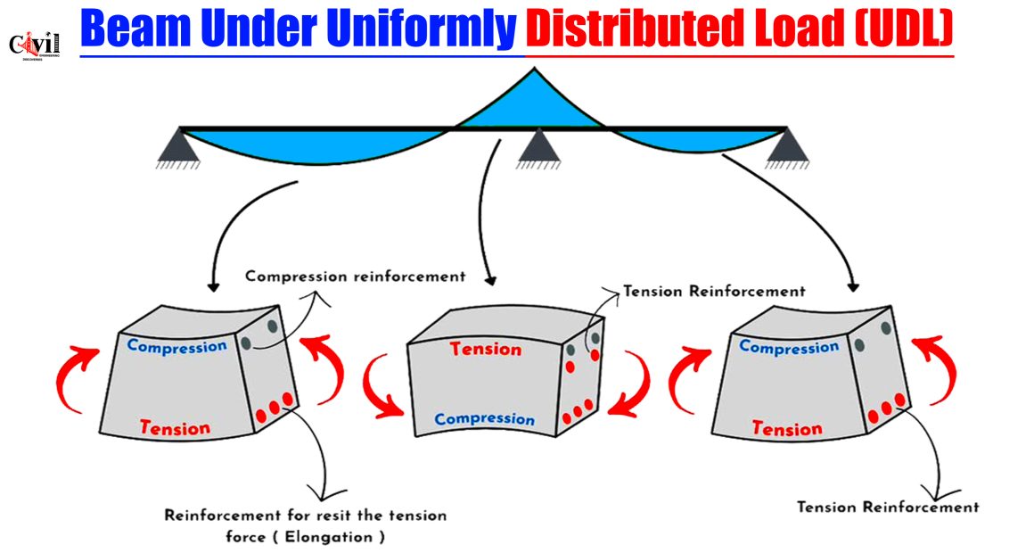
When a beam is subjected to UDL, it bends into a concave shape, typically downward in the middle. The bending moment diagram for a simply supported beam under UDL is a parabolic curve, peaking at mid-span. This deflection creates tensile stresses at the bottom fibers and compressive stresses at the top fibers of the beam.
At Mid-Span:
Tension occurs at the bottom of the beam.
Compression occurs at the top of the beam.
At Supports:
Shear force is at its maximum, and moment is zero.
Local reversal of stresses may occur in continuous beams or cantilevers.
Stress Zones in Beam Cross-Sections
To resist the internal moments and shears caused by UDL, the beam’s cross-section experiences a differentiated stress profile:
Top Fiber: Subjected to compressive forces.
Bottom Fiber: Experiences tensile forces.
Neutral Axis: Divides the tension and compression zones.
This stress differentiation demands reinforcement placement accordingly. Concrete is strong in compression but weak in tension, hence steel reinforcement is provided in the tensile zones.
Reinforcement Detailing in Beams under UDL
1. Tension Reinforcement
The main reinforcement is provided at the bottom of the beam to counter the tensile forces that occur due to downward bending at mid-span. This is especially important for simply supported beams.
Bars Used: High-yield deformed bars (HYSD), TMT bars.
Placement: Placed along the bottom length, with more concentration in mid-span.
Purpose: To resist elongation due to tension.
2. Compression Reinforcement
In some cases, such as deep beams or continuous beams, compression reinforcement is also introduced at the top of the section:
Purpose: To enhance the beam’s resistance to compression and help prevent failure due to over-compression or buckling.
Placement: Top layer, especially near supports or in regions of negative bending moments.
3. Shear Reinforcement (Stirrups)
Stirrups or links are crucial in resisting shear forces:
Location: Vertical or inclined stirrups are provided at closer spacing near the supports.
Function: Prevents shear failure or diagonal cracking.
Types of Beams and Reinforcement Strategies
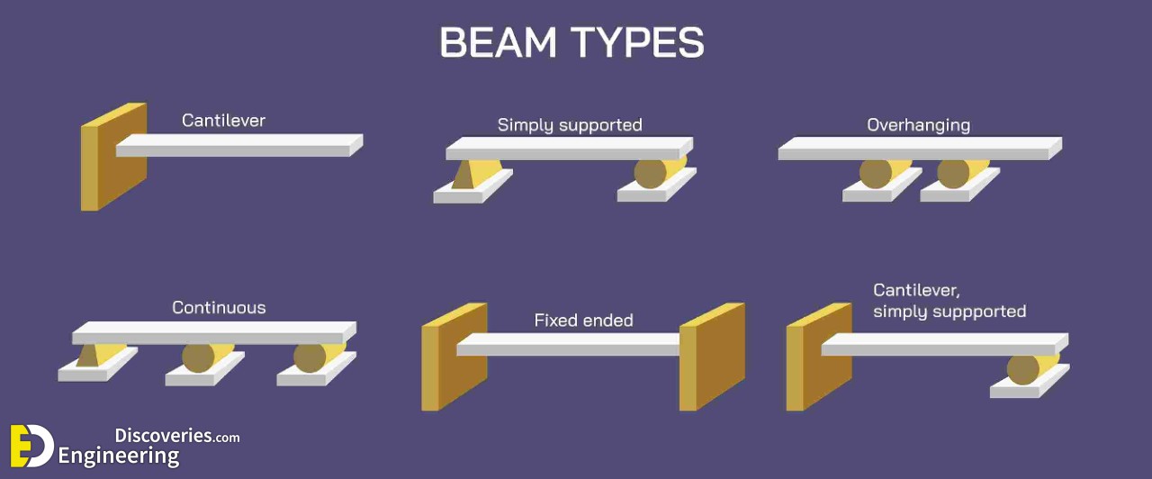
1. Simply Supported Beam
UDL creates maximum tension at mid-span.
Reinforcement is primarily needed at the bottom of the beam.
Standard detailing includes more bars in the center, tapering toward the supports.
2. Continuous Beam
Negative bending moment over supports.
Requires top reinforcement above supports and bottom reinforcement at mid-span.
Both compression and tension zones vary depending on span continuity.
3. Cantilever Beam
UDL induces maximum moment at the fixed support.
Tension reinforcement is provided at the top surface, and compression is at the bottom.
Design Considerations for UDL Beams
1. Span-to-Depth Ratio
A balanced ratio ensures that the beam is neither too deep (uneconomical) nor too shallow (prone to deflection).
2. Minimum Reinforcement
As per IS 456:2000 and other international codes, a minimum percentage of reinforcement must be provided, even if calculations show lesser demand, to handle shrinkage and temperature effects.
3. Concrete Grade and Steel Type
Higher grade concrete can resist higher compressive stress.
Use of Fe500 or Fe550 steel improves tensile resistance and allows for more slender beams.
Failure Modes in Beams Under UDL
Beams not properly designed or detailed for UDL can fail due to:
Flexural failure: Cracking in the tension zone due to inadequate reinforcement.
Shear failure: Diagonal cracks near supports.
Compression failure: Crushing of concrete at the top fiber due to insufficient concrete grade or poor compaction.
Proper detailing, quality materials, and code-compliant design prevent these failures.
Conclusion: Efficient Reinforcement Design is Key
An efficient beam design under UDL must ensure:
Adequate tensile reinforcement to resist sagging moments.
Compression reinforcement where necessary.
Proper shear reinforcement to tackle transverse loads.
Strategic placement of steel depends on stress zones, as visualized in the diagram.
Click Here To See 4 Important Rules When Designing A Concrete Torsion-Exposed Beam
