![Bar Bending Schedule [BBS] Estimate Of Steel In Building Construction](/_next/image?url=https%3A%2F%2Fengineeringdiscoveries.com%2Fwp-content%2Fuploads%2F2019%2F12%2FUntitled-1JLKMJLJLKLJ-scaled.jpg&w=3840&q=75)
Introduction to Bar Bending Schedule [BBS]
Bar bending schedule commonly known as BBS is one of the most important terms in Civil Engineering. Because it plays a vital role in building construction. Like other building materials estimation of steel is also required for constructing a building and here BBS comes with an easy solution. Bar bending schedule provides the reinforcement calculation and some other important details such as bar mark, bar diameter, bar shape, cutting length, number of bars, the weight of the bar, the total weight of steel etc. So that we can order the required amount of steel in advance.
Bar Bending Schedule [BBS]
Before dealing with the BBS, it’s very important to learn the basics of Bar bending schedule. The below-mentioned table is a kick-start guide for learning Bar bending schedule from scratch.
| S.No. | Particulars | Result |
|---|---|---|
| 1. | Standard Length of the Steel Bar (Bars are sold at standard Length) |
12m or 40′ |
| 2. | Weight of Bar for length = 1m |
D2/162
(were D = Dia of Bar) |
| Ex: | If the length of the bar is 12m with 10mm Dia then, Weight of bar = D2/162Therefore for length 1m = 1m x D2/162 = 1 x 10²/162 = 0.61 KgsFor length 12m = 12 x 102/162 = 7.40Kgs |
7.40Kgs |
| 3. | Density of Steel | 7850Kg/m3 |
1- Hook Length or Cutting length of Stirrups
The hook length is commonly provided for stirrups in beams and ties in columns. In general, Hooks are added at the two ends of the rebar in stirrups or ties.
Hook Length = 9d (d is dia of the bar)
Below image makes you clear why the Hook length = 9d
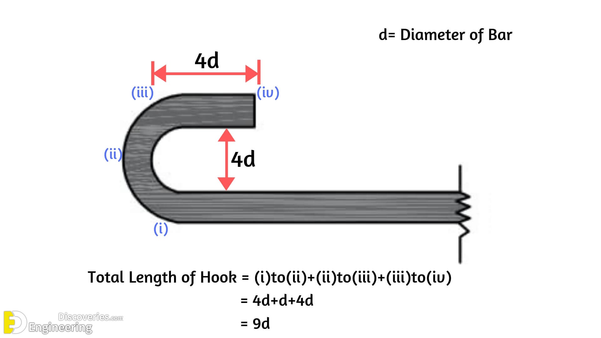
From above fig, length of hook = [(Curved Portion) + 4d] = [(4d+d)+4d] = 9d
Hook Length = 9d [d is Diameter of the Bar]
Example Calculation considering stirrup with the hooks at ends
For a clear understanding, look at the below image for calculation of the total length of stirrup the with two hooks at ends.
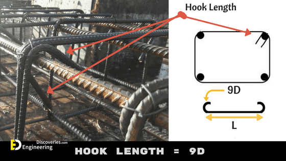
total Cutting Length of stirrup or tie = Total length of Bar + 2 x Hook Length (Two hooks)
Total Cutting Length = L+2(9d)
Therefore Total Cutting length = L+18d (d is the Diameter of a bar)
Hope, now you are clear with the Hook length calculation.
2- Bend Length
The Bend length calculation is different for Cranked bars (bent up bars) and bends at corners. The bars are usually cranked in Slabs and bars are bent at corners in Stirrups or ties.
(i) Bend Length calculation in Cranked Bars
As Shear stress is maximum at supports in Slab. To resist these stresses we usually crank the bars at the ends of supports in the slab. The below figure describes the bent up bar in Slab. To calculate the bend length the below procedure is followed.
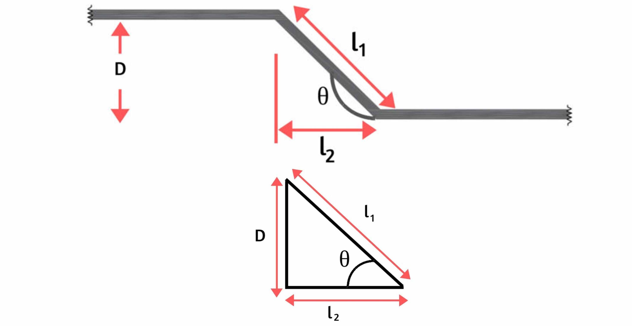
From the above figure as the bar is bent at an angle θ0 the additional length (la) is introduced.
Where, la = l1 – l2–(i)
Tanθ = D/l2 ; Sinθ = D/l1
Hence l1 = D/Sinθ and l2 = D/tanθ
Therefore from (i) :- la = D/Sinθ – D/tanθ
Giving different θ values as 300 , 450, 600 results different additional length la values as below.
| θ0 | D/Sinθ | D/tanθ | la =D/Sinθ – D/tanθ |
| 300 | D/0.500 | D/0.573 | 0.27D |
| 450 | D/0.707 | D/1.000 | 0.42D |
| 600 | D/0.866 | D/1.732 | 0.58D |
| 900 | D/1 | 0 | 1D |
| 1350 | D/0.707 | D/-1 | 2.42D |
The additional length is added to the total length of the bar if the bars are cranked at a certain angle.
Example Calculation considering Bent up bar in Slab (Cranked bar)
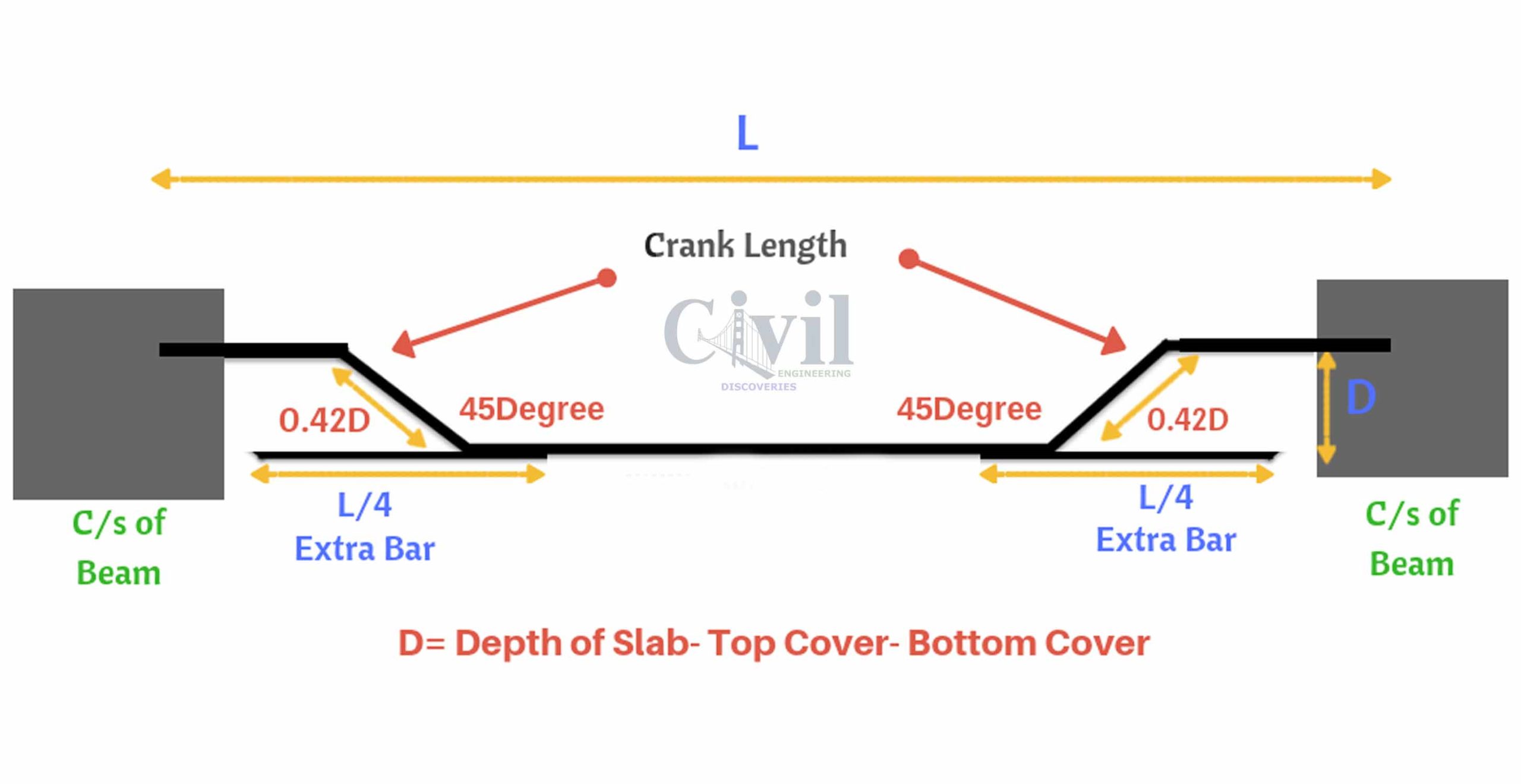
To keep the crank bar in position, an extra bar of length (L/4) is provided below the crank bar as shown in the below figure.
Therefore, the total length of bar = L+0.42D+0.42D+(L/4)+(L/4) = 1.5L+0.84D
Remember D = Depth of Slab-Top Cover-Bottom cover
(ii) Bend Length calculation when bars are bent at corners
The important standards used while calculating the bend length at corners
1- 45° Bend length = 1d
2- 90° Bend length = 2d
3- 135° Bend length = 3d
Here, ‘d’ = Diameter of bar
Example Calculation considering stirrup with the bends at corners
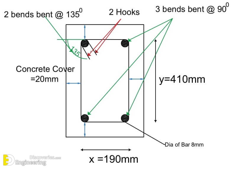
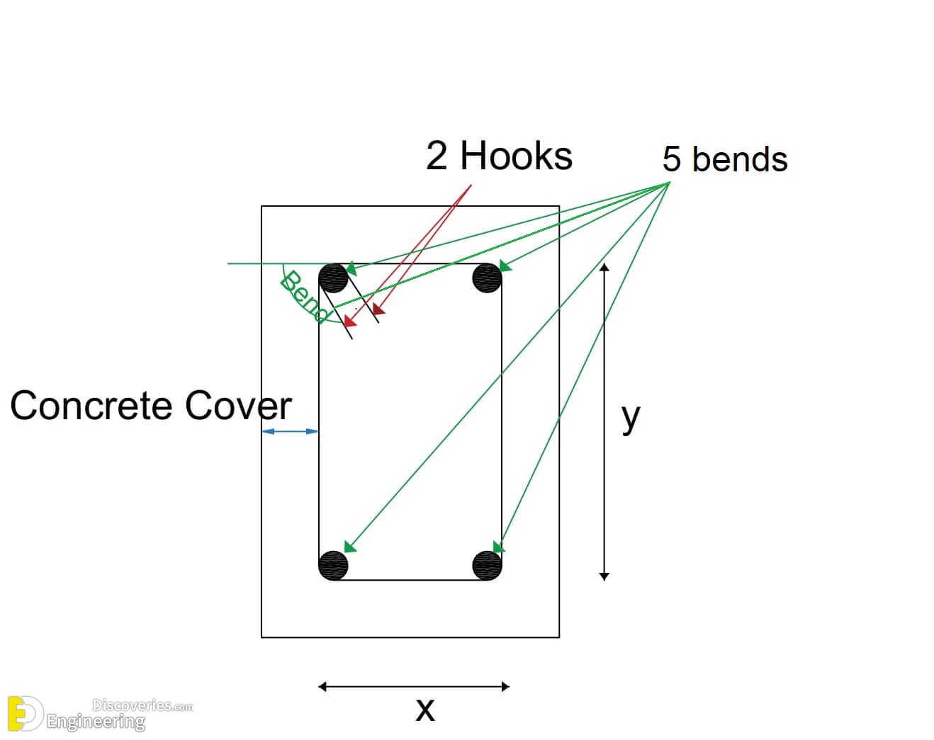
From above fig, There are 3 bends which are bent at an angle of 900 and two bends are bent at an angle of 1350
Total bend length = 3 x 900 Bend length + 2 x 1350 Bend length = 3 x 2d + 2 x 3d = 12d = 12 x 8 = 96mm
below table represents the total length of bar calculation for different types of bar shapes.
| Bar Shapes | Total Length of Hooks | Total Bend Length | Total Length of Bar |
|---|---|---|---|
Straight Bar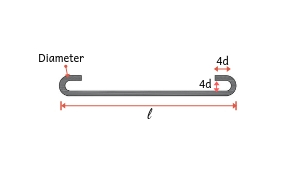 |
Two Hooks = 9d + 9d = 18d |
No bend | l + 18d |
Bent Up at one End only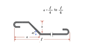 |
Two Hooks = 9d + 9d = 18d**d=Dia. |
One bend bent at an angle 45 = 0.42DRemember D = Depth of Slab-Top Cover-Bottom cover |
l + 18d + 0.42D |
Double Bent up Bar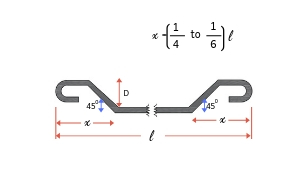 |
Two Hooks = 9d + 9d = 18d |
Two bends bent at an angle 450 |
l + 18d + 0.42D + 0.42D =l+18D+0.84D |
Overlap of bars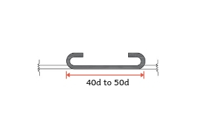 |
Two Hooks = 9d + 9d = 18d |
No bends | Overlap Length =(40d to 45d)+18d |
3- Overlap Length / Lap Length in Reinforcement
The standard length of Rebar is 12m. Suppose the height of the column is 20 m. To provide this requirement, two bars of length 12m and 8m are overlapped (joined) with overlap length.
Overlap Length for compression members (columns) = 50d
The Overlap Length for tension members (beams) = 40d
[d is the Diameter of the bar]

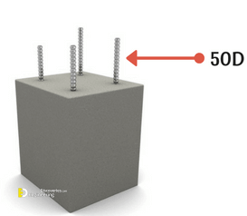
Have You seen the below picture on your top floor of the building? We generally project some length of Bar on the last floor i.e., 50D. It is used for further construction purpose. (Constructing a new floor)
How to Prepare Bar Bending Schedule
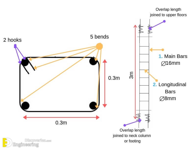
To understand clear, Here we considering the below structural member RCC Column and preparing a BBS +
| BBS of Column | |
|---|---|
| Structural Member | Column (3mx0.3mx0.3m) |
| Bar Marking | 1. Main Bars 2. Stirrups (Longitudinal bars) |
| Dia of Bar | 1. Main Bars = 16mm ; 2. Stirrups (Longitudinal bars) = 8mm |
| No. of Bars used | 1. Main bars = 4 2. Stirrups = 30 |
| Cutting length | 1. Main bars = 4.6m 2. Stirrups = 1.44m |
| Total Length of bar | 1. Main bars = 18.4m 2. Stirrups = 43.2m |
| Weight of Steel bar | 1. Main bars = 29Kgs 2. Stirrups =17Kgs |
Calculation part of the above table
No. of Bars calculation
Main bars = 4
To calculate the No. of longitudinal bars adopt spacing between bars is 0.1m
No. of Longitudinal bars = Length of column / Spacing = 3/0.1 = 30bars
Longitudinal bars = 30
Cutting length calculation:
Main bars = 3m + 50d + 50d = 3 + 50×0.016 + 50×0.016 = 4.6m
Stirrups:
Hook length = 9d + 9d = 18d = 18×0.08=1.44m
Bend length =3 x 900 Bend length + 2 x 1350 Bend length
= 3 x 2d + 2 x 3d = 12d = 12 x 8 =0.096m
= l +hook length + bend length = 0.3+0.3+0.3+0.3 +0.144+0.096=1.44m
Hence for Main Bars = 4.6m ; Longitudinal bars = 1.44m
Total Length of Bars:
The total length of Main bars = No. of Main bars x length of one bar
= 4 x 4.6 = 18.4m
The total length of the Longitudinal bars=No. of longitudinal bars x length of one bar
=30×1.44=43.2m
Weight of steel bar:
Weight of steel bar for 1m = 1m x D2/162
Total weight of Main bars = 18.4 x 162/162 = 29Kgs
Total weight of longitudinal bars = 43.2 x 82/162 =17Kgs
Total weight of steel bar required to do BBS of above column = 46Kgs
Important rules while preparing Bar Bending Schedule
1- The bars used in the building should be grouped together for each structural unit and listed separately for each floor.
2- Bars are listed in numerical order.
3- To identify the bar in the bundle of bars, each bar is uniquely labelled with reference details (Length of the bar, size of the bar, Shape of the bar)
4- The type of bar and shape of the bar should be in accordance with B8666.
5- It is essential that the bar mark reference on the label attached to a bundle of bars refers uniquely to a particular group or set of bars of defined length, size, shape and type used on the job.
6- The cutting length and bending length calculations are separately calculated and not included in the detailed list. Like I have listed the Bar Bending details in a table and calculations are done separately.
Use of Bar Bending Schedule
1- BBS helps to estimate the total quantity of steel required for the construction of building or structure. It helps to quote for tender the cost incurred by steel.
2- Finding the cutting length and bending length in reinforcement detailing improves the quality of construction and minimize the wastage of steel, makes an economic construction
3- With the help of reinforcement drawings, cutting and bending can be done at the factory and transported to the site. This increases faster construction and reduces the total construction cost.
4- For site engineers, It becomes easy to verify the cutting length and bending length of the reinforcement before placing the concrete.
Loading related articles...
Loading recent articles...
Loading featured articles...
