
Basic Electrical Symbols – Common
Basic electrical symbols like earth electrode, cell, battery, source, ideal source, resister, variable resister, pre-set resister, attenuator, capacitor, antenna, diode LED, crystal are included here.
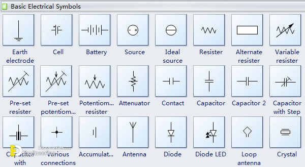
Earth electrode is a metal plate, water pipe, or another conductor of electricity partially buried in the earth so as to constitute and provide a reliable conductive path to the ground
Cell is a device containing electrodes immersed in an electrolyte, used for generating current or for electrolysis.
Battery is a container consisting of one or more cells, in which chemical energy is converted into electricity and used as a source of power.
Source is a part of a field-effect transistor from which carriers flow into the inter-electrode channel.
Ideal source includes an ideal voltage source and an ideal current source. An ideal source is a theoretical concept of an electric current or voltage supply (such as a battery) that has no losses and is a perfect voltage or current supply. Ideal sources are used for analytical purposes only since they cannot occur in nature.
Resistor is a device having resistance to the passage of an electric current.
Capacitor is a device used to store an electric charge, consisting of one or more pairs of conductors separated by an insulator.
The antenna is an electrical device that converts electric power into radio waves and vice versa.
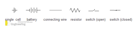
Some most commonly-used basic electrical symbols used in schematic diagrams are shown below:
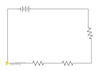
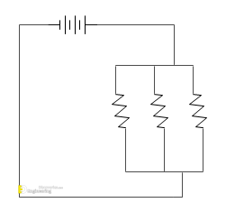
Let us take a look at how to use the basic electrical symbols to provide a schematic diagram of the circuit and its components. Example one: Three D-cells are placed in a battery pack to power a circuit containing three light bulbs. Each light bulb is represented by its own individual resistor symbol. Straight lines have been used to connect the two terminals of the battery to the resistors and the resistors to each other.
First, choose the electrical symbols you might use in the diagram, in this example is battery, resistor. Then, use the connector tool to connect these symbols. Therefore, the final diagram can be like the following picture.
Basic Electrical Switches and Relays Symbols
The picture below shows switches symbols. Switch 1P, isolator 1P, circuit breaker 1P, SPST, SPDT, DPST, DPDT, and more symbols are available here.
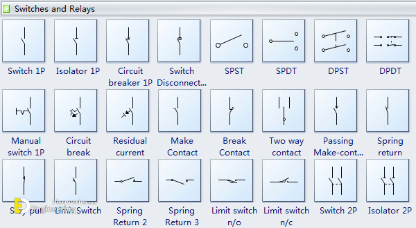
Switch is a device for making and breaking the connection in an electric circuit.
Isolator is a mechanical switch that isolates a part of the circuit from the system when required. Electrical isolators separate a part of the system from the rest for safe maintenance works.
SPST is a single-pole, single-throw (SPST) switch.
SPDT is single-pole, double-throw (SPDT) switch.
DPST is double-pole, single-throw(DPDT) switch.
DPDT is a double-pole, double-throw (DPDT) switch.
As you can see from the above pictures, using electrical symbols to draw electrical circuit diagrams is quite easy. To illustrate the method, we will give you another example of using basic electrical symbols. Example two: Three D-cells are placed in a battery pack to power a circuit containing three light bulbs.
First things first, quickly figure out what electrical symbols shall be used in the diagram. Then think about the layout of these symbols. Last but not least, use the connector tool to connect all the electrical symbols. Therefore, the final diagram can be like the following picture.
From the above examples, we can conclude that simple words can not clearly describe a specific electrical circuit. Using the basic electrical symbols to draw a circuit diagram can show the manners in which the circuit components are placed.
Basic Electrical Transmission Path Symbols
The picture below shows transmission path symbols like wire, multi-line bus, straight bus, junction, terminal, test point, label, outwear flow, inward flow, etc.
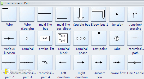
Wire is used to connect the components in a circuit.
Test point is a location within an electronic circuit that is used to either monitor the state of the circuitry or to inject test signals.
Outward flow means flowing outwardly, so inward flow means flowing inwardly.
Click Here To See What Are Those Balls That Hang On Power Lines?
Loading related articles...
Loading recent articles...
Loading featured articles...
