Introduction to Structural Beam Design
Structural beam design ensures buildings and infrastructure remain stable and safe. Beams are horizontal or inclined members that support loads and transfer forces within a structure. Proper design minimizes failure risks while optimizing performance.
Key Considerations in Beam Design
1. Load Calculation
Engineers begin by determining the loads that the beams must support. These include:
- Dead Loads – Permanent weights such as walls, flooring, and fixed equipment.
- Live Loads – Variable loads like occupants, furniture, and vehicles.
- Environmental Loads – Wind, snow, seismic forces, and other external factors.
2. Material Selection
Beams are made from different materials based on structural needs:
- Steel – High strength and ductility.
- Concrete – Durable and fire-resistant.
- Timber – Lightweight and sustainable.
- Composite Materials – Hybrid combinations for enhanced performance.
3. Bending and Shear Stress Analysis
Beams experience two primary stresses:
- Bending Stress – Caused by applied loads, leading to deflection.
- Shear Stress – Concentrated near supports and connection points.
4. Beam Sizing
Engineers determine the beam’s cross-sectional dimensions based on stress analysis, ensuring it supports loads without excessive deflection or failure.
5. Code Compliance
Building codes, such as the International Building Code (IBC) and Eurocodes, set minimum safety and performance standards for beam design.
6. Connection Design
Beams connect to columns, foundations, or other beams. Proper connection design ensures load transfer and overall stability.
7. Deflection Control
Excessive deflection affects occupant comfort and finish durability. Engineers limit deflection within acceptable thresholds for safety and performance.
8. Economic Considerations
Optimized beam design balances material cost and structural efficiency, reducing expenses while maintaining integrity.
9. Construction Considerations
Fabrication, transportation, and installation influence beam design. Engineers must ensure beams are practical for real-world construction.
10. Safety Factors
Engineers apply safety margins to account for uncertainties in material properties, construction conditions, and unexpected loading scenarios.
Diagram Symbols in Beam Design
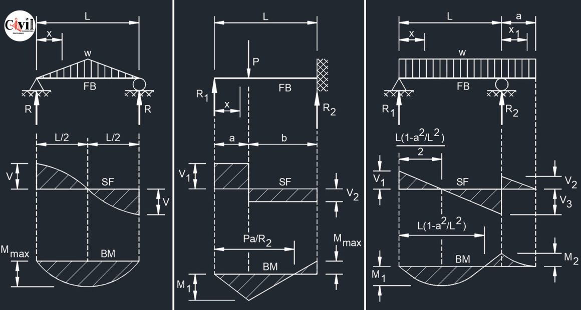
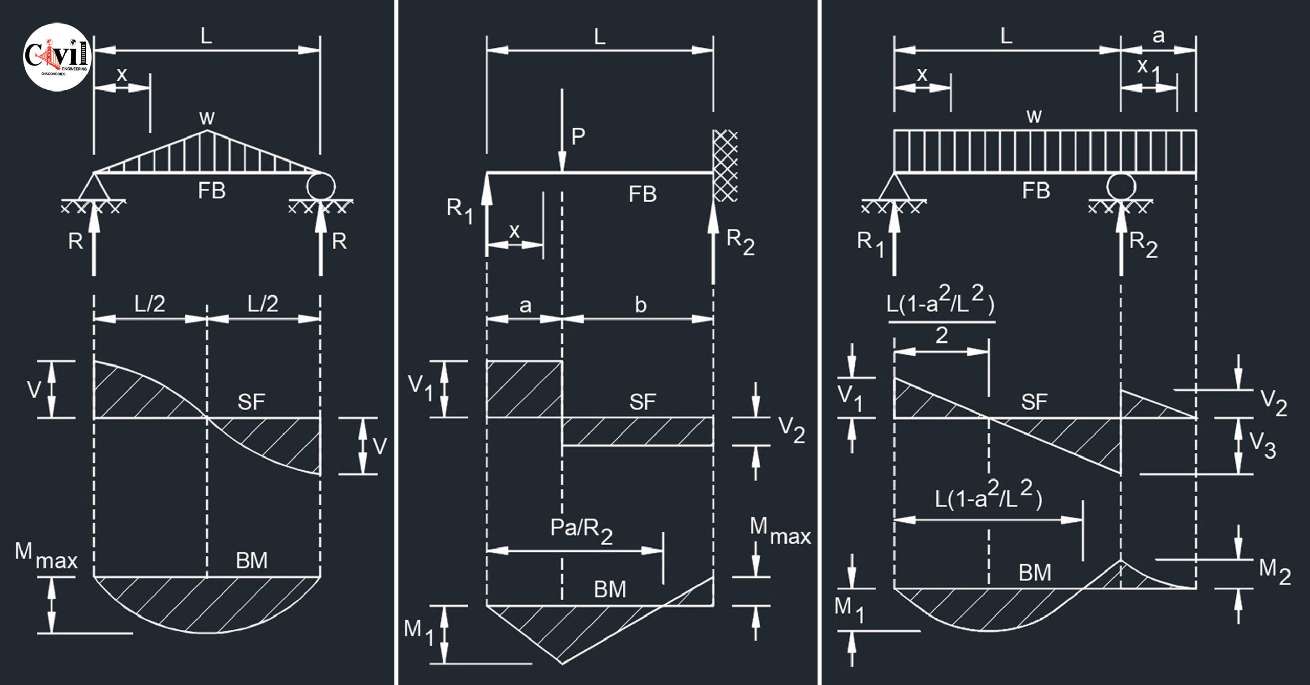
Bending Moment Diagram (BMD)
A graphical representation of bending moments at various beam points. It helps determine the beam’s required strength and material selection.
Free Body Diagram (FBD)
Illustrates forces, moments, and reactions acting on a beam. Essential for structural analysis and design verification.
Shear Force Diagram (SFD)
Shows shear force distribution along a beam’s length. Helps in determining where shear reinforcements are necessary.
Uniformly Distributed Load (UDL)
A load spread evenly across a beam’s length is commonly found in floors and bridges.
Simple Supported Beam
Beam Fixed at One End
Beam Fixed at Both Ends
Cantilever Beam
Overhanging Beam
Two Span Continuous Beam
Three Span Continuous Beam
Four Span Continuous Beam
