
Combined footings are constructed for two or more columns when they are close to each other and their foundations overlap. The design of combined footings with examples is discussed.
The function of a footing or a foundation is to transmit the load from the structure to the underlying soil. The choice of a suitable type of footing depends on the depth at which the bearing strata lies, the soil condition, and the type of superstructure.
Combined Footings:
Whenever two or more columns in a straight line are carried on a single spread footing, it is called a combined footing. Isolated footings for each column are generally economical.
Combined footings are provided only when it is absolutely necessary, as:
1. When two columns are close together, causing overlap of adjacent isolated footings
2. Where soil bearing capacity is low, causing overlap of adjacent isolated footings
3. Proximity of building line or existing building or sewer, adjacent to a building column.
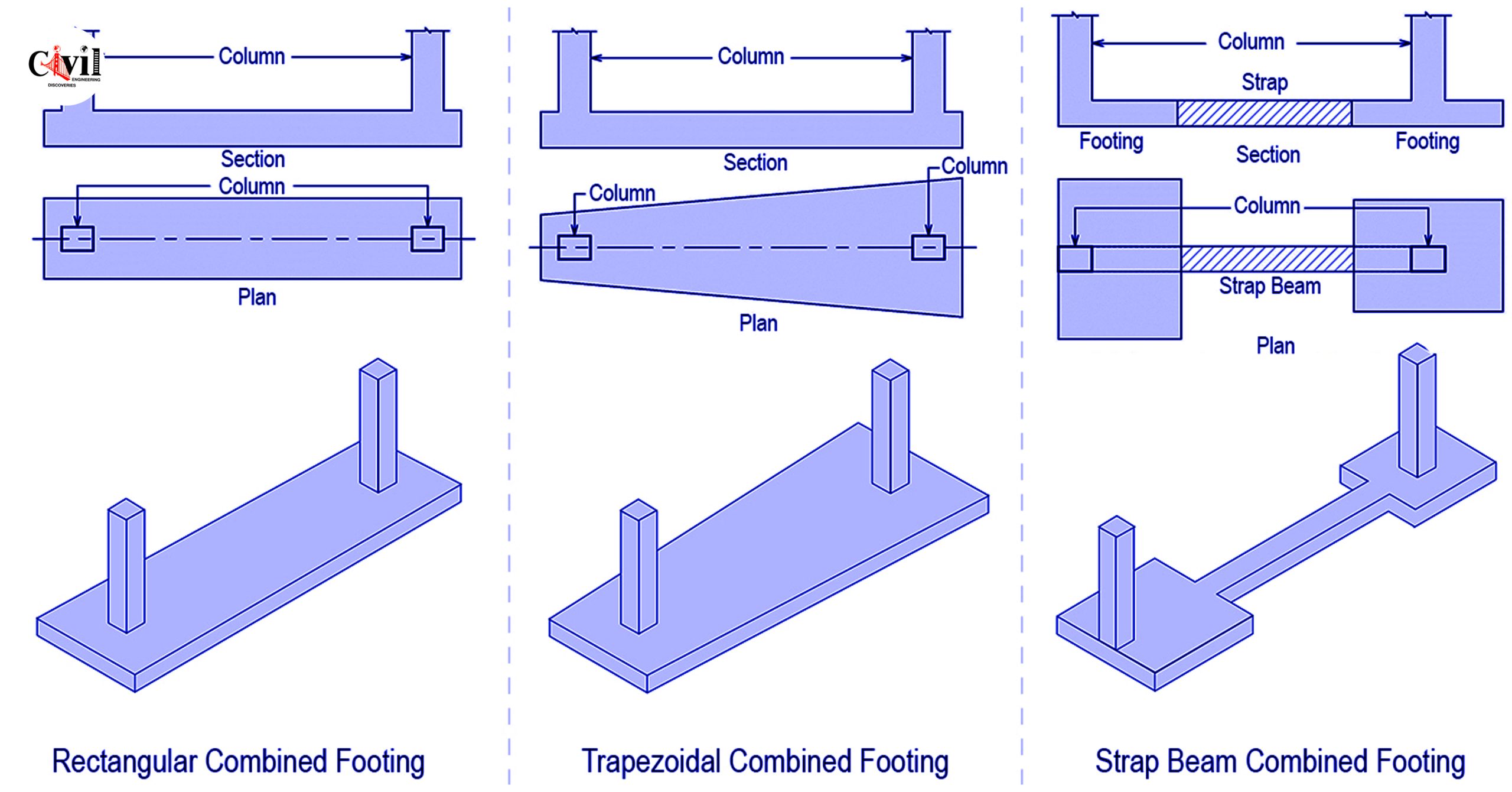
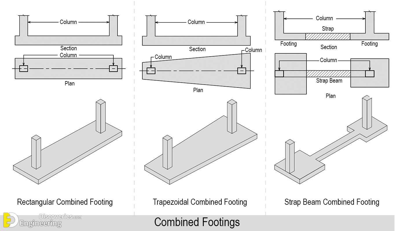
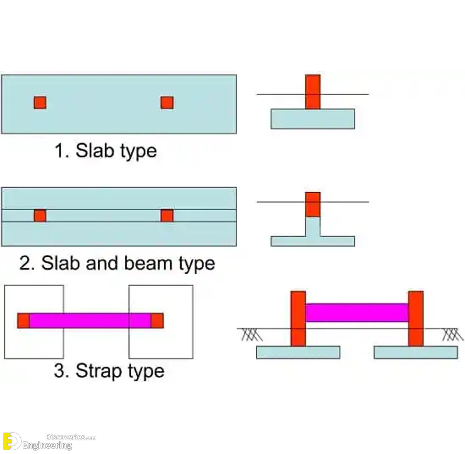
Types of Combined Footing
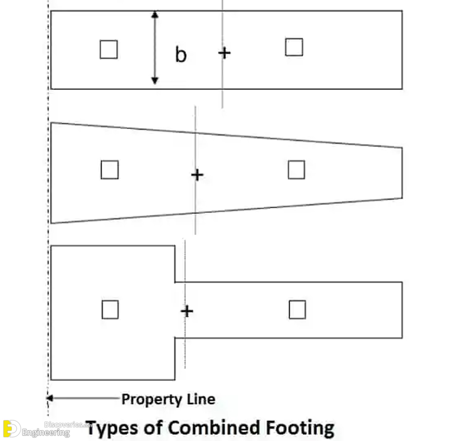
- The combined footing may be rectangular, trapezoidal, or Tee-shaped in plan.
- The geometric proportions and shape are so fixed that the centroid of the footing area coincides with the resultant of the column loads. This results in uniform pressure below the entire area of the footing.
- Trapezoidal footing is provided when one column load is much more than the other. As a result, both projections of the footing beyond the faces of the columns will be restricted.
- Rectangular footing is provided when one of the projections of the footing is restricted or the width of the footing is restricted.
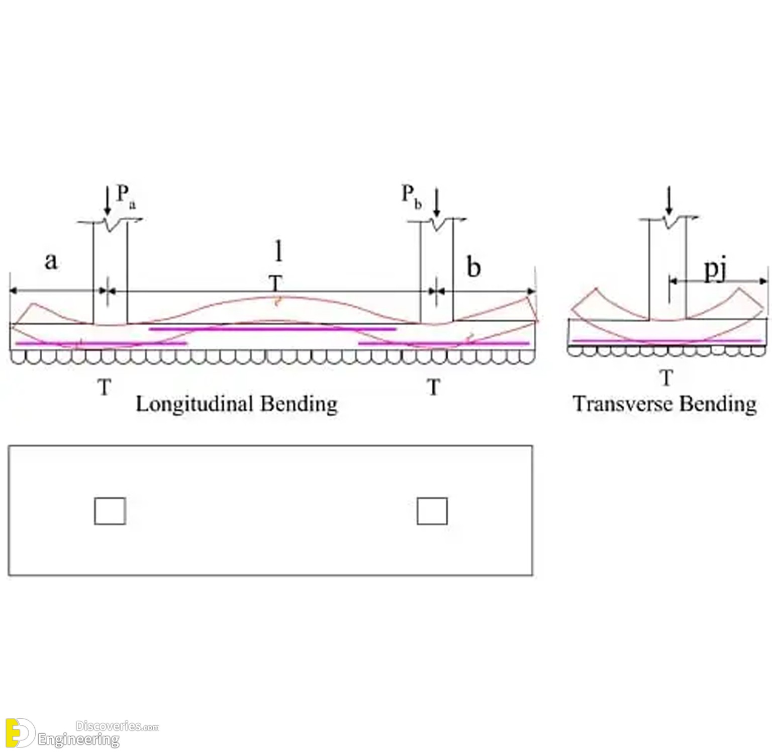
Rectangular combined footing
- Longitudinally, the footing acts as an upward-loaded beam spanning between columns and cantilevering beyond. Using statics, the shear force and bending moment diagrams in the longitudinal direction are drawn. The moment is checked at the faces of the column. Shear force is critical at a distance ‘d’ from the faces of columns or at the point of contra flexure. Two-way shear is checked under the heavier column.
- The footing is also subjected to transverse bending and this bending is spread over a transverse strip near the column.

Steps for Design of Combined Footing:
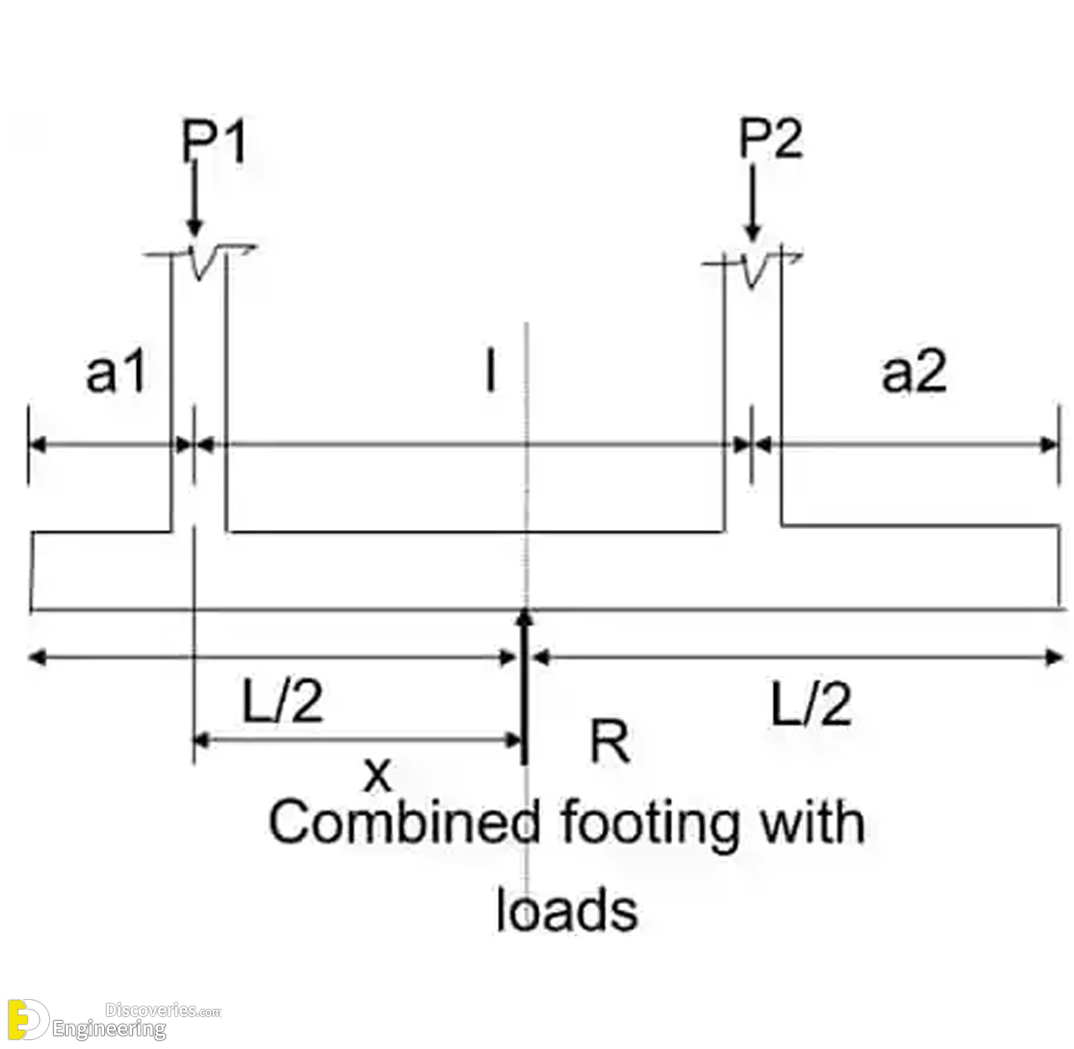
- Locate the point of application of the column loads on the footing.
- Proportion the footing such that the resultant loads pass through the center of the footing.
- Compute the area of footing such that the allowable soil pressure is not exceeded.
- Calculate the shear forces and bending moments at the salient points and hence draw SFD and BMD.
- Fix the depth of footing from the maximum bending moment.
- Calculate the transverse bending moment and design the transverse section for depth and reinforcement. Check for anchorage and shear.
- Check the footing for longitudinal shear and hence design the longitudinal steel
- Design the reinforcement for the longitudinal moment and place them in the appropriate positions.
- Check the development length for longitudinal steel
- Curtail the longitudinal bars for economy
- Draw and detail the reinforcement
- Prepare the bar bending schedule
Detailing of Combined Footing
Detailing of steel (both longitudinal and transverse) in a combined footing is similar to that of conventional beam-SP-34. Detailing requirements of beams and slabs should be followed as appropriate-SP-34