1- CFA Piles (Auger Cast)
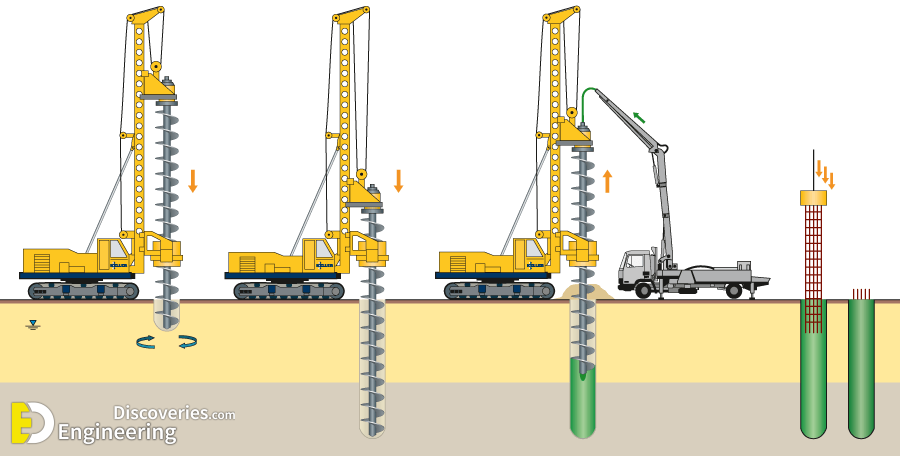
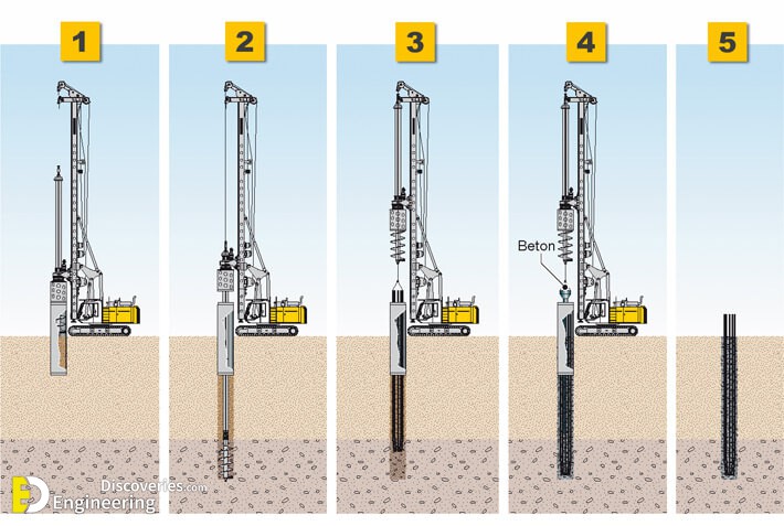
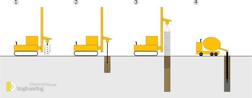
CFA Piles, also known as continuous flight auger piles or auger cast piles, are cast-in-place piles, using a hollow stem auger with continuous flights.
Technical Details
The auger is drilled into the soil and/or rock to design depth. The auger is then slowly removed with the drilled soil/rock as concrete or grout is pumped through the hollow stem.
The grout pressure and volume must be carefully controlled to construct a continuous pile without defects. Reinforcing steel is then lowered into the wet column. The finished foundation element resists compressive, uplift, and lateral loads.
2- Drilled Shafts
Drilled shafts, also known as caissons, are high-capacity, cast-in-place elements constructed using an auger. Whether as isolated columns or a secant/tangent wall
Technical Details
A hole with the design diameter of the planned shaft is first drilled to the design depth. If the hole requires support to remain open, casing or drilling fluid is used. Full-length reinforcing steel is then lowered into the hole which is then filled with concrete. The finished foundation element resists compressive, uplift, and lateral loads.
3- Driven Piles
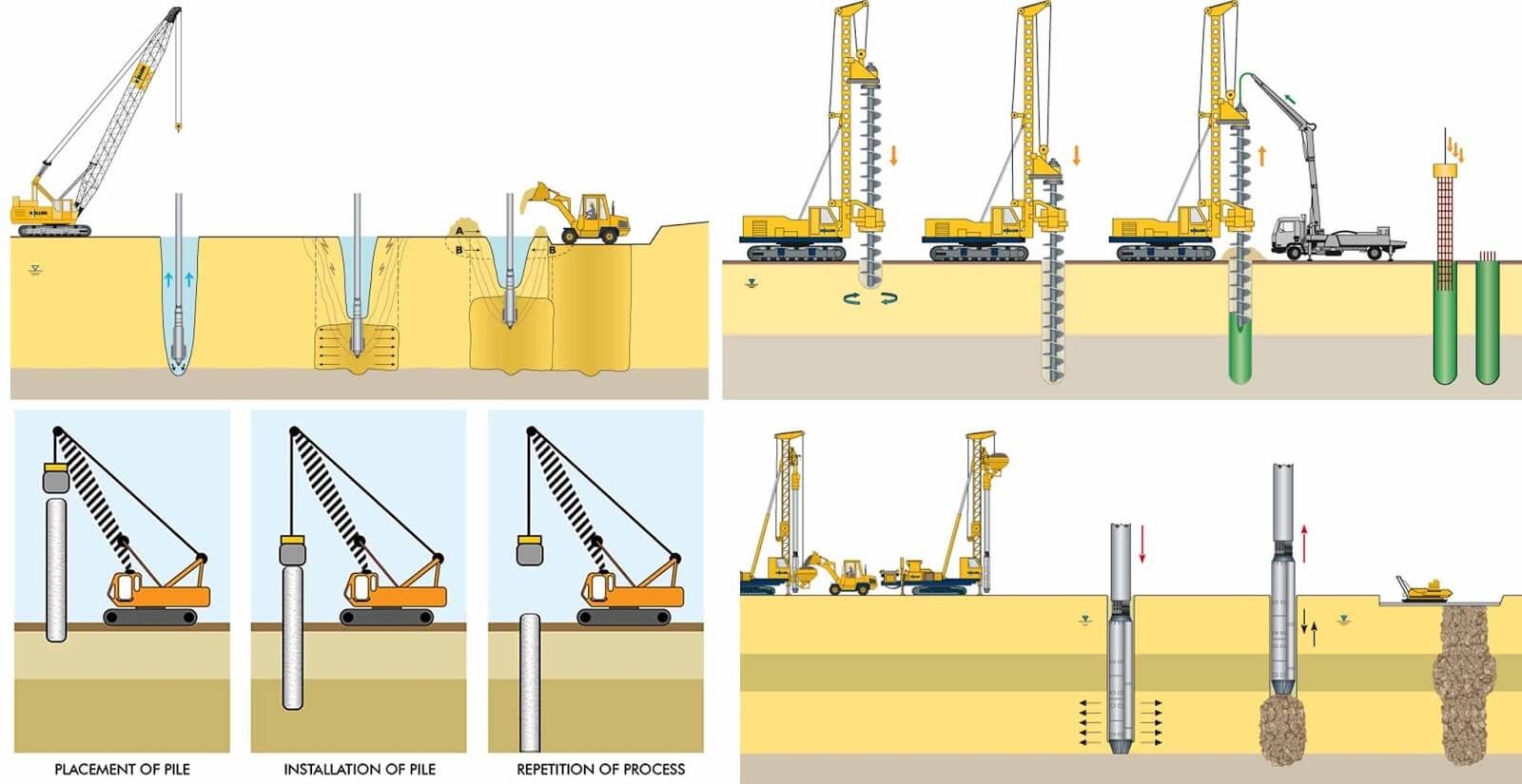
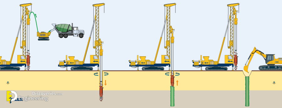
Driven Piles are installed using impact or vibration hammers to a design depth or resistance.
Technical Details
If penetration of dense soil is required, pre-drilling may be required for the pile to reach the design depth. Types include timber, pre-cast concrete, steel H-piles, steel sheet piles, and pipe piles. The finished foundation element is designed to resist compressive, uplift, and/or lateral loads. Driven piles can be used to provide lateral support for earth retention walls. Steel sheet piles and soldier piles are the most common type of driven piles for this application.
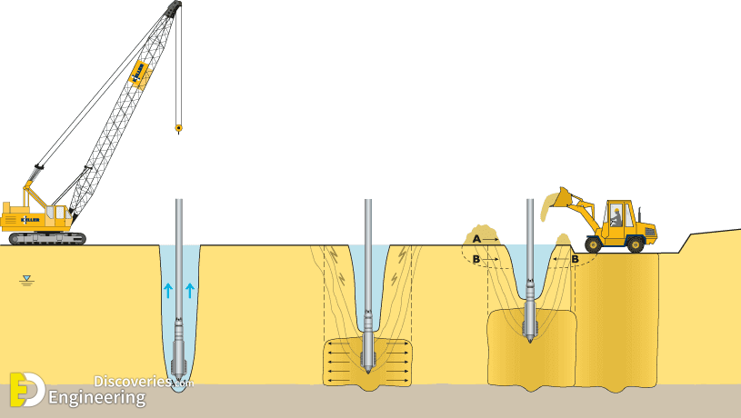
4- Franki Piles (PIFS)
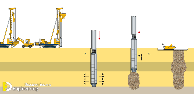
Franki Piles, also known as Pressure Injected Footings (PIFS), are high-capacity, cast-in-place elements constructed using a drop weight and casing.
Helical piles, also known as helical piers, are constructed using steel shafts with helical flights. Whether for light or heavy loads.
Technical Details
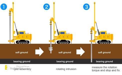
The shafts are advanced to bearing depth by twisting them into the soil while monitoring torque to estimate the pile capacity. A detailed understanding of the subsurface conditions is necessary to properly interpret the torque conversion. After reaching design capacity, the tops of the shafts are connected to the structure’s foundation.
6- Jacked Piers
Jacked piers are constructed using small-diameter steel pipes advanced to bearing depth by hydraulic jacks that are secured to the structure being underpinned.
Technical Details
Using the structure as the reaction load, the jack hydraulic pressure required to advance the pile verifies the pile capacity. This method essentially load tests each pile. After reaching bearing depth, the tops of the pipes are bracketed to the structure’s footing.
7- MacroPiles
A macropile is an ultra-high-capacity micropile typically drilled in place.
Technical Details
Typically, a steel pipe is advanced using a drilling technique to the design depth. In cases where the drill hole remains open without casing, an open hole can be advanced to the bearing depth and the pipe installed after. Reinforcing steel in the form of an all-thread bar or concentric pipes is inserted into the pipe.
High-strength cement grout is then pumped into the pipe(s) by tremie. The pipe tip may be above the bond zone with the reinforcing steel extending full depth. The finished foundation element resists compressive, uplift, and lateral.
8- Micropiles
Micropiles are a deep foundation element constructed using high-strength, small-diameter steel casing and/or threaded bar.
Technical Details
Micropiles are also known as minipiles, pin piles, needle piles, and root piles. The micropile casing generally has a diameter in the range of 3 to 10 inches. Typically, the casing is advanced to the design depth using a drilling technique. Reinforcing steel, typically an all-thread bar is inserted into the micropile casing. High-strength cement grout is then pumped into the casing.
The casing may extend to the full depth or end above the bond zone with the reinforcing bar extending to the full depth. The finished micropile (minipile) resists compressive, uplift/tension, and lateral loads and is typically load tested in accordance with ASTM D 1143 (compressive), ASTM D 3689 (uplift/tension), and ASTM D 3966 (lateral). Capacities vary depending on the micropile size and subsurface profile. Allowable micropile compressive capacities of more than 500 tons have been achieved.
9- Pit Underpinning
Pit underpinning is a traditional underpinning technique that stabilizes structures prior to adjacent excavation, using concrete and mortar.
