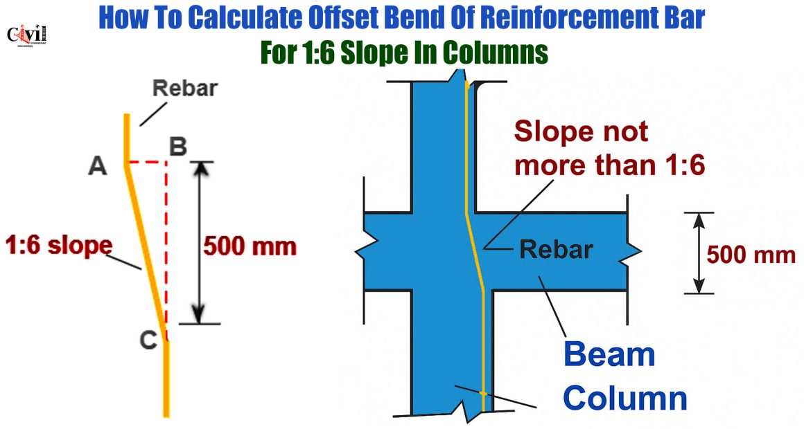
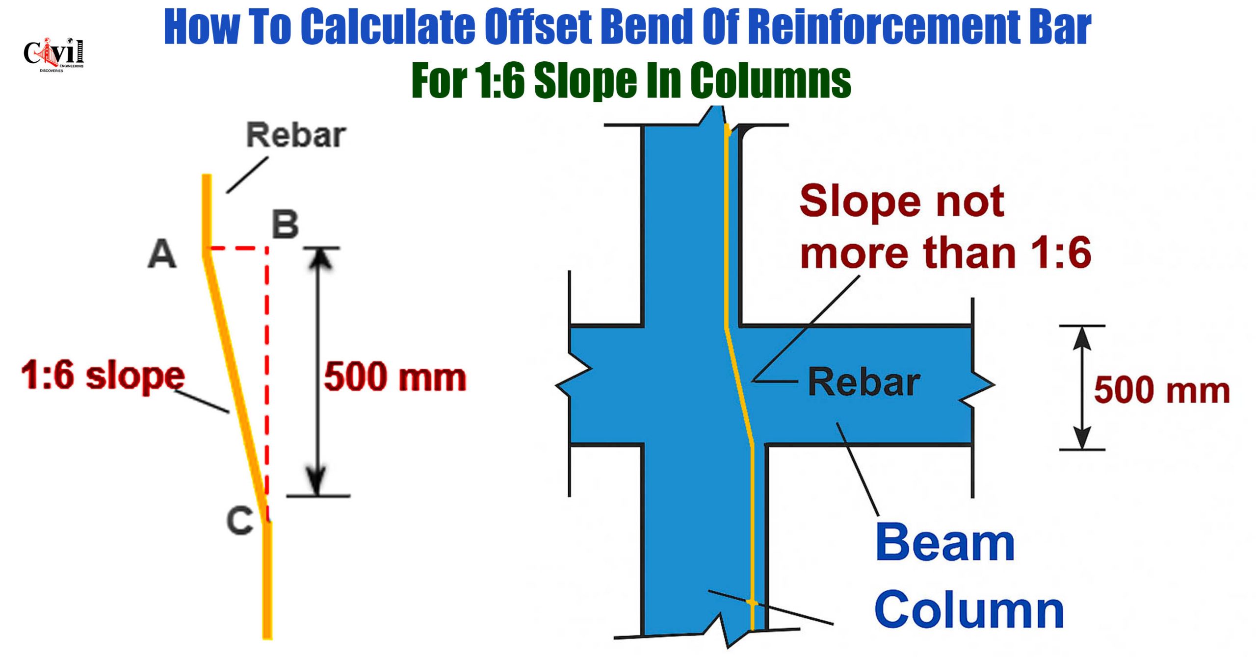
Multi-story construction projects require precise reinforcement calculations. Understanding offset bend calculations becomes crucial for structural integrity. This comprehensive guide explains the step-by-step process for calculating reinforcement bar offset bends.
Understanding Column Size Reduction in Multi-Story Buildings
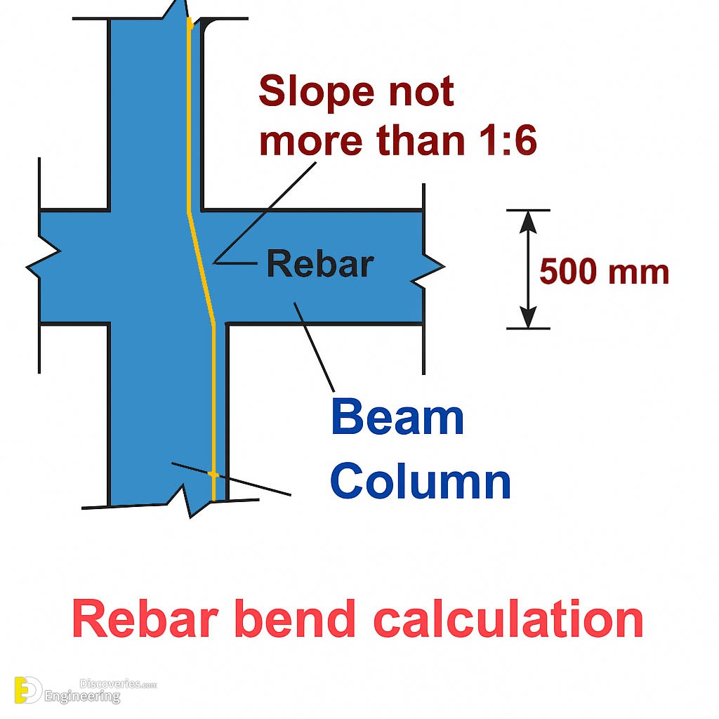
Multi-story buildings typically feature reduced column dimensions on upper floors. Consequently, architects design smaller columns to optimize space usage. Meanwhile, structural engineers must ensure proper reinforcement continuity.
Column width reduction occurs from one side only. Thus, reinforcement bars require precise bending at specified slopes. Moreover, accurate calculations prevent structural failures and ensure building safety.
What is Reinforcement Bar Offset Bending?
Offset bending refers to the angular displacement of reinforcement bars. Subsequently, this technique accommodates column size changes between floors. Furthermore, proper offset calculations maintain structural continuity throughout the building height.
Engineers commonly use 1:6 slope ratios for offset bends. Additionally, this ratio provides an optimal balance between structural requirements and construction practicality. However, different projects may require varying slope ratios based on specific design needs.
Essential Parameters for Offset Bend Calculations
Key Measurements Required
Several critical measurements determine accurate offset calculations. First, beam depth significantly influences the bending length. Second, the specified slope ratio affects the horizontal offset distance. Third, reinforcement bar diameter impacts the overall bending requirements.
Professional engineers always verify these parameters before beginning calculations. Additionally, structural drawings provide essential dimensional information. Moreover, building codes specify minimum requirements for reinforcement continuity.
Understanding the 1:6 Slope Ratio
The 1:6 slope ratio represents a specific angular relationship. Specifically, for every six units of vertical length, one unit represents horizontal offset. Therefore, this ratio creates approximately 9.46 degrees of inclination.
This slope ratio ensures gradual load transfer between column sections. Furthermore, it prevents stress concentrations that could compromise structural integrity. Meanwhile, construction workers can easily achieve this slope during installation.
Step-by-Step Calculation Method
Given Parameters for Sample Calculation
Consider the following project specifications:
- Beam depth: 500mm
- Required slope: 1:6 ratio
- Standard reinforcement bar diameter
These parameters form the foundation for accurate offset calculations. Subsequently, engineers apply mathematical formulas to determine precise measurements.
Horizontal Offset Distance Calculation
The fundamental formula for offset calculation follows basic trigonometric principles. Therefore, the relationship becomes:
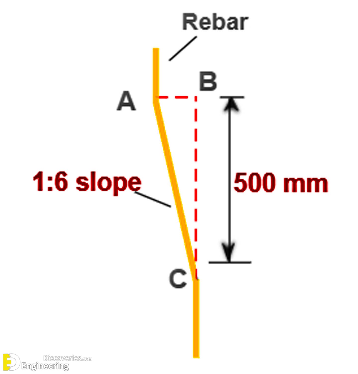
AB / BC = 1/6
Where AB represents horizontal offset and BC represents vertical beam depth.
Substituting the given values: AB / 500 = 1/6
Solving for AB: AB = (1/6) × 500 = 83.33mm
This calculation provides the required horizontal offset distance. Consequently, reinforcement bars must bend 83.33mm horizontally over the 500mm vertical distance.
Bent Portion Length Calculation
Calculating the actual length of the bent reinforcement section requires the Pythagorean theorem. Thus, the diagonal length represents the true bent portion measurement.
Length of AC = √(AB² + BC²)
Substituting calculated values: Length of AC = √(83.33² + 500²) Length of AC = √(6,944 + 250,000) Length of AC = √256,944 Length of AC = 506.9mm
Practical Application Considerations
Construction Site Implementation
Field applications require careful attention to measurement accuracy. Additionally, construction teams must use appropriate bending tools for consistent results. Moreover, quality control procedures ensure compliance with design specifications.
Experienced reinforcement workers understand the importance of gradual bending. Furthermore, sharp bends can create stress concentrations and potential failure points. Therefore, smooth transitions maintain structural integrity.
Quality Control Measures
Regular inspection ensures proper implementation of calculated offsets. Subsequently, project supervisors verify measurements against approved drawings. Meanwhile, documentation records maintain quality assurance standards.
Professional engineers recommend frequent spot checks during construction. Additionally, photographic documentation provides evidence of proper installation techniques. Moreover, correction procedures address any deviations from specifications.
Common Calculation Errors to Avoid
Measurement Accuracy Issues
Precision becomes critical in reinforcement calculations. Therefore, rounding errors can accumulate and affect structural performance. Furthermore, using inappropriate measurement units creates significant discrepancies.
Professional practice requires consistent unit usage throughout calculations. Additionally, verification checks prevent costly construction errors. Moreover, double-checking calculations ensures accurate results.
Formula Application Mistakes
Incorrect formula application leads to structural inadequacies. Subsequently, engineers must understand the underlying mathematical principles. Meanwhile, software tools can assist with complex calculations while maintaining accuracy.
Click Here To See Calculate Cutting Length Of Bent Up Bar In Slab
