Step NO. 01: Sizes
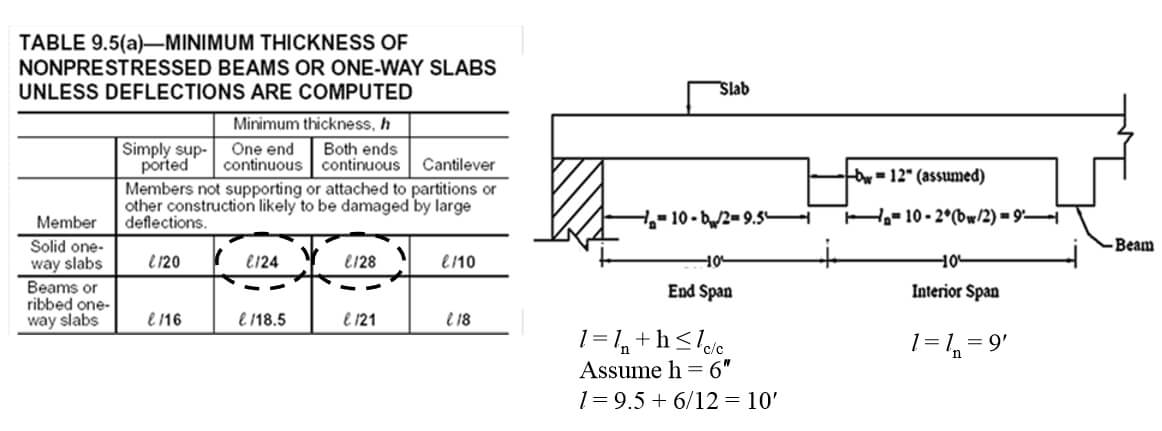
h = l/24 × (0.4+fy/100000) = 4″ (Minimum by ACI for end span
y h = l/28 × (0.4+fy/100000) = 3″ (Minimum by ACI for interior span)
End span governs. Finally take assumed h = 6″
Effective depth (d) = hf – 0.75 – (3/8)/2 = 5″ (for #3 main bar)
Step NO. 02: Loads
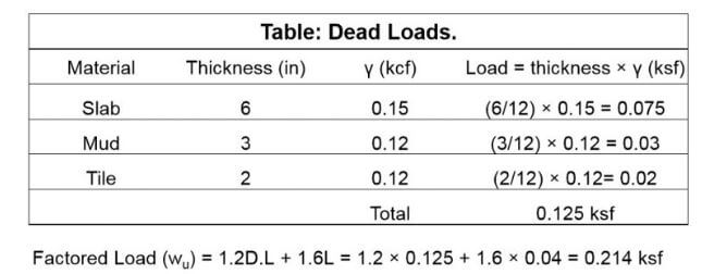
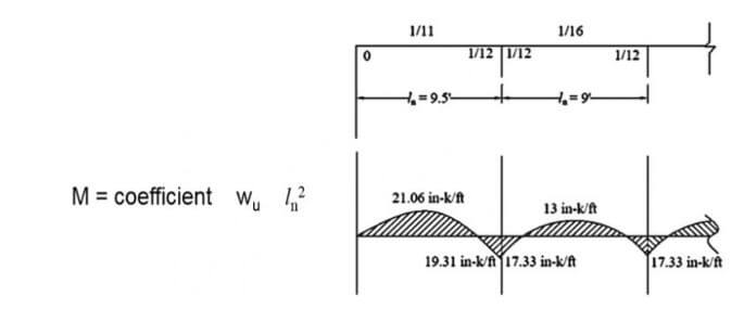
Step NO. 03: Analysis
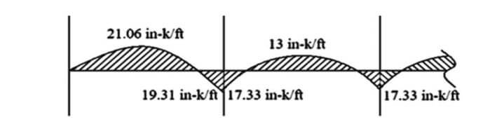
Bending moment diagram for slab
Step NO. 04: Design
Calculate Moment Capacity Provided by Minimum Reinforcement in Slab:
Asmin = 0.002bhf = 0.002 × 12 × 6 = 0.144 in2/ft
ΦMn = ΦAsminfy (d-a/2) = 0.9 × 0.144 × 40 × (5-0.188/2) = 25.4 in-k/ft
Φ Mn calculated from Asmin is > all moments calculated in Step No 3.
Therefore As = Asmin = 0.144 in2/ft (#3 @ 9.166″ c/c)
This will work for both positive and negative steel as Asmin governs.
Main Reinforcement Spacing:
Maximum spacing for main steel reinforcement in one way slab according to ACI 7.6.5 is minimum of:
3hf = 3 × 6 =18″
18″ z Finally use, #3 @ 9″ c/c.
Shrinkage Steel or Temperature Steel (AST):
Ast = 0.002bhf Ast = 0.002 × 12 × 6 =0.144 in2/ft
Shrinkage reinforcement is the same as the main reinforcement, because:
Ast = Asmin = 0.144 in2
Maximum spacing for temperature steel reinforcement in one way slab according to ACI 7.12.2.2 is minimum of:
5hf =5 × 6 =30″ OR 18″ z Therefore 9″ spacing is O.K.
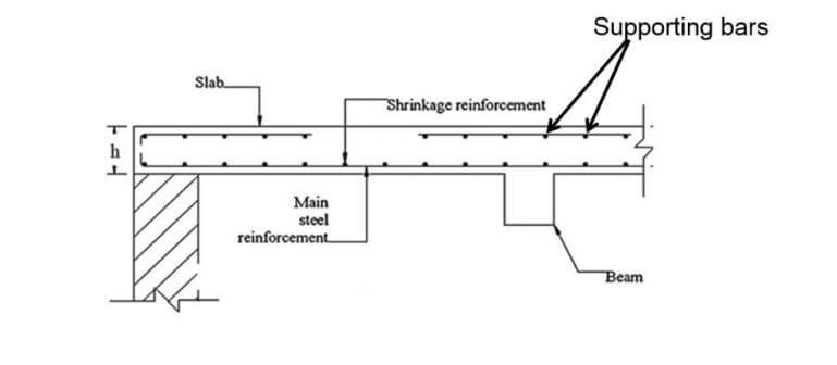
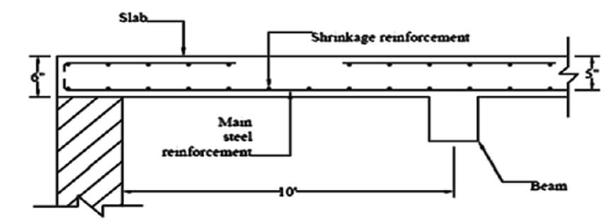
Step NO. 05: Drafting
Main reinforcement = #3 @ 9″ c/c (positive & negative)
Shrinkage reinforcement = #3 @ 9″ c/c
Supporting bars = #3 @ 18″ c/c