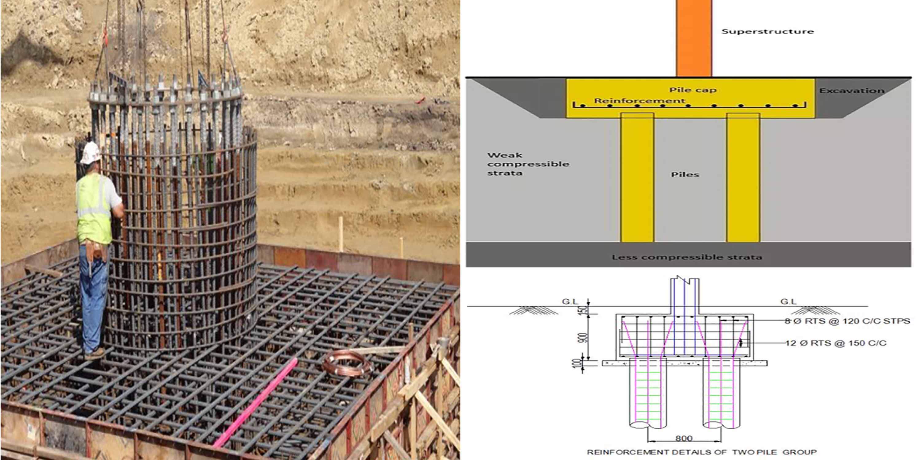
WhatIs Pile cap
A pile cap is a thick concrete mat that rests on concrete or timber piles that have been driven into the soft or unstable ground to provide a suitable stable foundation. It usually forms part of the foundation of a building, typically a multi-story building, structure or support base for heavy equipment. The cast concrete pile cap distributes the load of the building into the piles. A similar structure to a pile cap is a “raft”, which is a concrete foundation floor resting directly onto soft soil which may be liable to subsidence.
As per IS 2911 (Part I/ Sec 3) -2010, the pile cap may be designed by assuming
that the load from the column is dispersed at 45˚ from the top of the cap up to the mid-depth of the pile cap from the base of the column or pedestal. The reaction from
piles may also be taken to be distributed at 45˚ from the edge of the pile, up to the
mid-depth of the pile cap. On this basis, the maximum bending moment and shear
forces should be worked out at critical sections.
Assumptions Involved In The Design Of Pile Caps
1- The pile cap is perfectly rigid.
2- Pile heads are hinged to the pile cap and hence no bending moment is transmitted to piles from pile caps.
3- Since the piles are short and elastic columns, the deformations and stress distribution are planers.
Design Parameters Of Pile Caps
1- Shape of the pile cap.
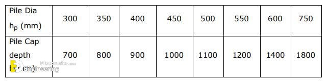
2- Depth of pile cap.
3- Amount of steel to be provided.
4- Arrangement of reinforcement.
Practical Aspects on Pile cap Design
1- The size of the pile cap is fixed in such a way that it has a clear overhang beyond
the outermost pile is not less than 100mm, but preferably 150mm.
2- It should be deep enough to allow the necessary overlap of reinforcements from
column and piles.
3- The clear cover to the main reinforcement should not be less than 40mm.
4- The span to thickness ratio of the cap should not be more than 5 so that the pile cap
is rigid enough to distribute the load uniformly to the piles.
5- Generally, its thickness should not be less than 500mm which may be reduced to
300mm at the free edges.
6- The piles should be at least 50mm into the pile cap.
7- A leveling course of not less than 75mm thick concrete should be provided under the
pile cap.
Design Aspects
The reaction from the piles under the concentric axial load on the cap is
assumed equal and is determined by
Pp = Q/n —– (1)
where Q = concentric axial load on the cap
n = Number of Piles
When the Pile cap is eccentrically loaded or subjected to a load and moments
then the reactions from the Piles are determined as
Pp = Q/n +/- My x÷∑xˆ2 +/- Mx y÷∑yˆ2 —– (2) where
Mx, My = moments with respect to x and y axes.
X, y = distances from y and x-axes to the Piles.
The critical section for bending moments and bond shall be calculated at the face of the column or pedestal. The critical section for two-way shear (Punching shear) will be at a distance d/2 from the face of the column or pedestal. One-way shear is checked at a distance of d/2 from the face of the column. Clause 34.2.4.2 of IS 456 – 2000 states the following:-
“In computing the external shear or any section through a footing supported on
Piles, the entire reaction from any pile of diameter Dp whose center is located
Dp/2 or more outside the section shall be assumed as producing shear on the
section, the reaction from any Pile whose center is located Dp/2 or more inside
the section shall be assumed as producing no shear on the section. For intermediate positions of the pile center, the position of pile reaction to being assumed as producing shear on the section shall be based on straight-line interpolation between the full value at Dp/2 outside the section and zero value at
Dp/2 inside the section.” In computing external shear on any section, the entire (100%) reaction of the Pile shall be taken if the pile center is located at 150 mm or more outside the section. The pile reaction will produce no shear (0%) if the pile centre is located
at 150 mm or more inside the section. Linear interpolation shall be made for intermediate values of the pile center. Let the center of the pile be located at ‘x’ from the face of the column. Let’s be the effective depth of the pile cap. Then the critical section is located at d/2 from the face of the column.
If pile centre is located at (d/2 –x) outside the critical section when x< d/2.
If x > d/2, the expression (d/2-x) yields a negative value indicating that
the pile center is located at (x-d/2) inside the section. When
(d/2-x), outside is true for another case. Let the fraction of pile reaction inducing shear be f R where R is the pile reaction. Rule for checking one way shear
f = (150 +(x-d/2))/ 300 , where x and d are in millimeters.
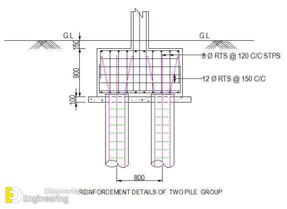
Design Of Two Pile Cap
DATA:-
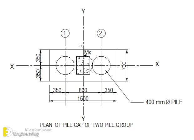
Pile Diameter = 400 mm
Spacing of piles 2 hp ⇒ 2 x 400 = 800 mm
Column Dimension B x D = 300 x 450 mm
Factored Load =1072.8 KN
Factored Moment Mxu = 51.29 KN.m
Safe Load on Single Pile =500KN
Concrete Mix = M20
Steel Grade = Fe 415
Design: –
1. Pile Cap Dimension
Breadth of Pile Cap = C/c of Pile + hp /2+ 150 + hp /2 + 150
= 800 + 400/2+ 150 +400/2+ 150 =1500 mm
Width of pile cap = hp + 150 + 150 = 700 mm
Depth of Pile cap = 2 hp + 100 = 2 x 400 + 100 = 900 mm.
2. Check for Pile Load capacity
Total factored axial compressive load
= Pu/n +/- Mx y÷∑y² +/- Mx x÷∑x²
Self weight of Pile Cap = (1.5 x0.7 x 0.9 x 25 ) x1.5 = 35.45 KN
Factored load from column Pu = 1072.80 KN
Total Factored Load Pu⇒ 35.45 + 1072.80 = 1108.25 KN
No. of Piles along one side of axis = 2
y coordinate of Pile cap = 0.4 m
Mx = Moment about x axis = 51.29 KN.m
Compressive load in A1 & A2 about x – x axis
= 1108.25/2 + 51.29 x 0.4/2 x 0.42
= 554.13 + 64.11
=618.24 KN
Design working load = 618.24 /1.5 = 412.16 KN < Safe Load on Pile i.e 500KN. O.K.
3. Bending Moment
Factored Moment in section Y-Y
Mu = 618.24 x (0.8-0.3)/2= 154.56 KN.m
4. Check for effective depth
Mu = 0.138 fck b d² = 154.56 x 10ˆ6
d required = √ (154.56 x 10ˆ6 ) / 2.76 x700 =282.84 mm
D provided = 900 mm
d available = 900 – 60 -12- 6 = 822 mm > d required i.e. 282.84 mm
5. Check for Punching Shear (Two way shear)
Punching shear at a distance d/2 (i.e.822/2= 411mm) from the face of the column
= 1072.80 KN
The critical section of punching comes to the center of the pile.
Hence the net load is to be taken. However the depth is checked for factored axial load from column = 1072.80 KN
b= 700 x 822 mm
d= 822 mm
Perimeter of critical section = 2 (700 + 822) = 3044 mm
Punching shear stress = 1072.80 x 10ˆ3/3044×822 = 0. 43 N/mm2
Allowable shear stress for M20
= 0.25 √fck = 0.25 √20 = 1.12 N/mm2
Hence safe.
6. Main Reinforcement
Mu = 154.56 x 10ˆ6 KN.m
K = Mu / bdˆ2 = 154.56 x 10ˆ6 /700×822ˆ2= 0.33
Pt from Table 2 of Design Aid=0.11
Minimum Ast = 0.12/100 x 700 x 822 = 690.48 mmˆ2
Provide 7 Nos. 12 Φ RTS at bottom on both ways.
(Ast = 791 mmˆ2 > 690.48 mmˆ2)
Reinforcement at top :
Minimum Ast = 0.12/100 x 700 x 822 = 690.48 mmˆ2
Provide 7 Nos. 12 mm Dia RTS at top .
(Ast = 791 mmˆ2 > 690.48 mmˆ2 )
7. Check for one way shear
Maximum Shear force at face of column = 618.24 KN
Shear stress = 618.24 x 10ˆ3/700×822 = 1.07 N/mmˆ2
For Pt = 0.20%
ζc from Table 61 of Design Aid to IS 456 -1978 = 0.33 N /mm2 Shear to be carried by stirrups shear
Vus =(1.07– 0.33) x700 x822 x 10ˆ-3 = 425.80 KN.
Vus /d = 425.80 / 82.2 = 5.18 KN/cm
Provide 8 Φ RTS 4 legged stirrups @ 120 mm c/c.
(Vus /d =5.58 KN/m > 5.18 KN/cm ).
8. Sketch