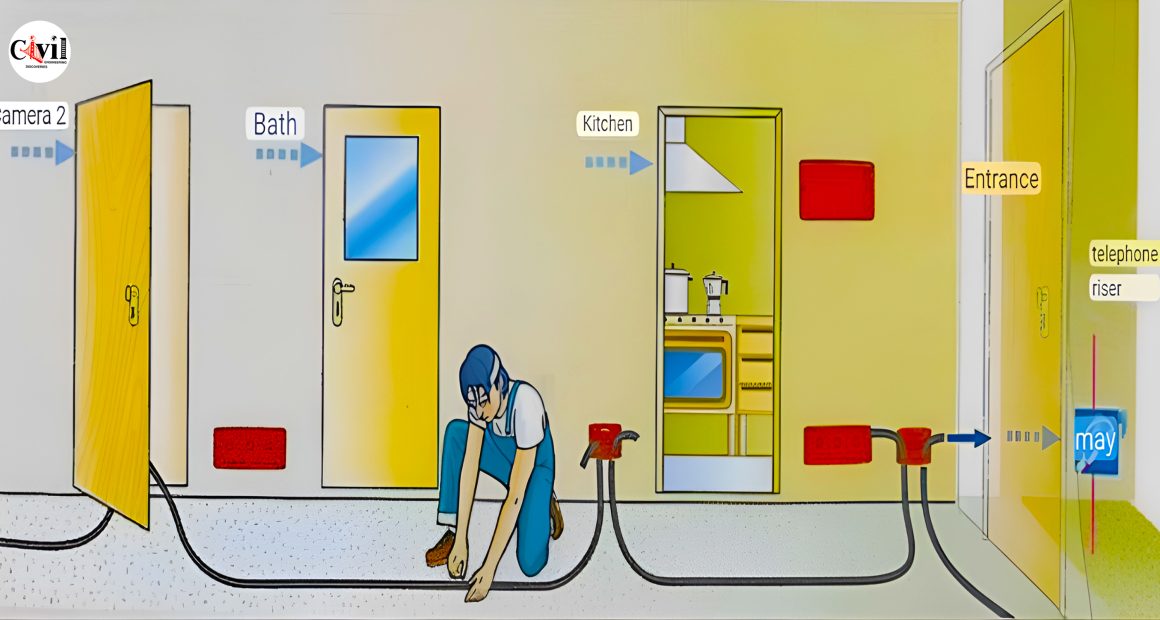
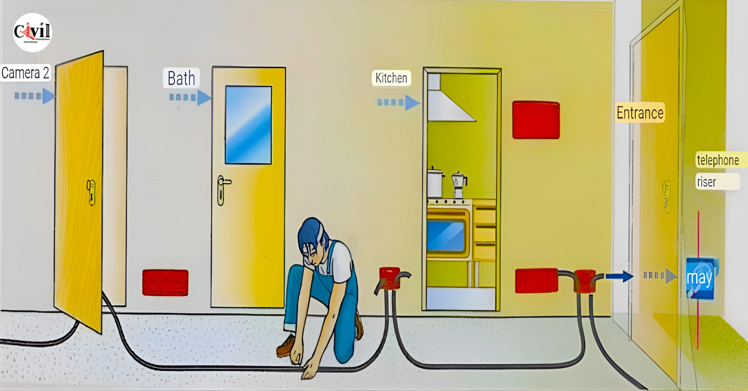
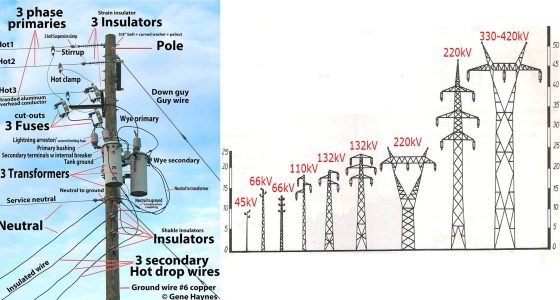
The electrical house plan is a drawing that shows the layout and wiring of a house. It includes the locations of outlets, switches, lights, appliances, and other electrical devices. It also shows the connections between the circuits and the panel. An electrical house plan is useful for planning, installing, or renovating electrical systems in a home.
There are some standards and guidelines that you should follow when creating or reading an electrical house plan. Some of them are:
- Use symbols and labels to represent the electrical components and their types. For example, a circle with an X inside means a duplex receptacle, a circle with a C inside means a ceiling fan and a zigzag line means a light fixture. You can find a list of common electrical symbols here.
- Use dashed lines to show which switches control which lights or receptacles. For example, a dashed line from a switch to a light means that the switch can turn on or off the light.
- Use different colors or line types to distinguish different types of wires. For example, black wires are usually hot, white wires are usually neutral, and green wires are usually ground. You can also use labels or numbers to identify the wire size and gauge.
- Use a scale and a legend to show the dimensions and orientation of the house plan. For example, 1/4 inch = 1 foot means that every quarter inch on the plan represents one foot in reality. You can also use a compass or an arrow to show the north direction.
- Include information about the circuit breakers, fuses, wattage, voltage, and amperage of the electrical system. For example, you can show the number and rating of the breakers in the panel, the number and size of the circuits, and the total load and demand of the system.
Click Here To See How Much Watts Solar Panel Do You Need For Home Appliances?


